PIPE AND PIPE MATERIALS
There are seven classifications of pipe materials contained in the code:
1. Water-service pipe: This type of pipe may be made of asbestos cement, brass, cast iron, copper, plastic, galvanized iron, or steel.
2. Water-distribution pipe: This type of pipe may be made of brass, copper, plastic, or galvanized steel.
3. Above-ground drainage and vent pipe: This type of pipe may be made of brass, cast iron, type K, L, M, or DWV copper, galvanized steel, or plastic.
4. Underground drainage and vent pipe: This type of pipe can be made of brass, cast iron, type K, L, M, or DWV copper, galvanized steel, or plastic.
5. Building-sewer pipe: This type of pipe may be made of asbestos cement, bituminized fiber, cast iron, type K or L copper, concrete, plastic, or vitrified clay.
6. Building-storm-sewer pipe: This type of pipe may be made of asbestos cement, bituminized fiber, cast iron, concrete, type K, L, M, or DWV copper, or vitrified tile.
7. Subsoil-drain pipe: This type of pipe may be made of asbestos cement, bituminized fiber, cast iron, plastic, styrene rubber, or vitrified clay.
More specific uses of piping for heating purposes are included in the following material. Also make sure to review your knowledge of insulating pipes.
Insulation
Insulation is needed to prevent the penetration of heat through a wall or air hole into a cooled space. There are several insulation materials, such as wood, plastic, concrete, and brick. Each has its application. How- ever, more effective materials are constantly being developed and made available.
Sheet Insulation
Vascocel® is an expanded, closed-cell, sponge rubber that is made in a continuous sheet 36 inches wide. It comes in a wide range of thicknesses: (3/8, 1/2, and 3/4 inches). This material is designed primarily for insulating oversize pipes, large tanks and vessels, and other similar medium- and low-temperature areas. Be- cause of its availability on continuous rolls, this material lends itself ideally to application on large air ducts and irregular shapes.
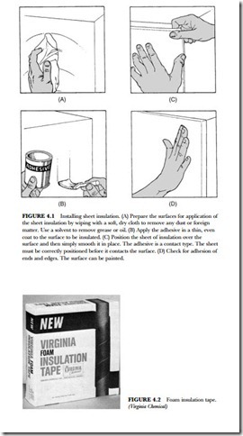
This material is similar to its companion product, Vascocel® tubing. It may be cut and worked with or- dinary hand tools such as scissors or a knife. The sheet stock is easily applied to clean, dry surfaces with an adhesive. (See Figure 4.1.) The k factor (heat-transfer coefficient) of this material is 0.23. It has some advan- tages over other materials: it is resistant to water penetration, water absorption, and physical abrasion.
Tubing Insulation
Insulation tape is a special synthetic rubber and cork compound designed to prevent condensation on pipes and tubing. It is usually soft and pliable. Thus, it can be molded to fit around fittings and connections. There are many uses for this type of insulation. It can be used on hot or cold pipes or tubing. It is used in residential buildings, air-conditioning units, and commercial installations. It comes in 2-inch-wide rolls that are 30 feet long. The tape is thick. If stored or used in temperatures under 90 degrees F [32.2 degrees C], its lifetime is indefinite.
Foam-insulation tape is made specifically for wrapping cold pipes to prevent pipe sweat. (See Figure 4.2.) It can be used to hold down heat loss on hot pipes below 180 degrees F [82.2 degrees C]. It can be cut in
(Virginia Chemical)
pieces and easily molded around fittings and valves. It adheres to itself and clean metal surfaces. It is wrapped over pipes with about 1/4 inch overlap on each successive lap. Remember one precaution: never wrap two or more parallel runs of tubing or pipe together, leaving air voids under the tape. Fill the voids be- tween the pipes with Permagum® before wrapping. This will prevent moisture from collecting in the air spaces. This foam-insulation tape has a unicellular composition. The k factor is 0.26 at 75 degrees F [23.9 degrees C].
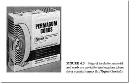
Permagum® is a non hardening, water-resistant sealing compound. It is formulated to be non staining and non bleeding and to have excellent adhesion to most clean surfaces. It comes in containers in either slugs or cords. (See Figure 4.3.)
This sealer is used to seal metal to metal joints in air conditioners, freezers, and coolers. It can seal metal to wood joints and set plastic and glass windows in wood or metal frames. It can be used to seal electrical or wire entries in air-conditioning installations or in freezers. It can be worked into various spaces. It comes with a paper backing so that it will not stick to itself.
Extrusions are simple to apply. Unroll the desired length and smooth it into place. It is soft and pliable. The bulk slug material can be formed and applied by hand or with tools such as a putty knife.
Pipe Fittings
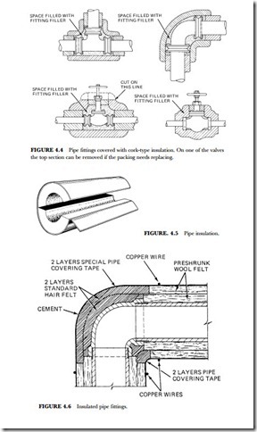
Pipe fittings are insulated for a number of reasons. Methods of insulating three different fittings are shown in Figure 4.4. In most cases it is advisable to clean all joints and waterproof them with cement. A mixture of hot crude paraffin and granulated cork can be used to fill the cracks around the fittings.
Figure 4.5 shows a piece of rock-cork insulation. It is molded from a mixture of rock wool and waterproof binder. Rock wool is made from limestone that has been melted about 3,000 degrees F [1,649 degrees C]. It is then blown into fibers by high pressure steam. Asphaltum is the binder used to hold it into a moldable form. This insulation has approximately the same insulation qualities as cork. It can be made waterproof when coated with asphalt. Some more modern materials have been developed to give the same or better in- sulation qualities. Vascocel® tubing can be used in the insulation of pipes. Pipe wraps are available to give good insulation and prevent dripping, heat loss, or heat gain.
Figure 4.6 shows a fitting insulated with preshrunk wool felt. This is a built-up thickness of pipe covering made of two layers of hair felt. The inside portion is covered with plastic cement before the insulation ma- terial is applied. After the application, waterproof tape and plastic cement should be added for protection against moisture infiltration. This type of insulation is used primarily on pipes located inside a building. If the pipe is located outside, another type of insulation should be used.
Refrigeration Piping
Various materials have been used for insulation purposes in the refrigeration field. It is this equipment that service people are most often called to repair or maintain. It is therefore necessary for the present-day repair- person to be acquainted with the older types of insulation that may be encountered during the workday.
The success of any refrigeration plant depends largely on the proper design of the refrigeration piping and a thorough understanding of the necessary accessories and their functions in the system. In sizing refrigerant lines, it is necessary to consider the optimum sizes with respect to economics, friction losses, and oil return. It is desirable to have line sizes as small as possible from the cost standpoint. On the other hand, suction- and discharge-line pressure drops cause a loss of compressor capacity, and excessive liquid-line pressure drops may cause flashing of the liquid refrigerant with consequent faulty expansion-valve operation.
Refrigerant piping systems, to operate successfully, should satisfy the following:
• Proper refrigerant feed to the evaporators should be ensured.
• Refrigerant lines should be of sufficient size to prevent an excessive pressure drop.
• An excessive amount of lubricating oil should be prevented from being trapped in any part of the system.
• Liquid refrigerant should be prevented from entering the compressor at all times.
Pressure-Drop Considerations
Pressure drop in liquid lines is not as critical as it is in suction and discharge lines. The important thing to remember is that the pressure drop should not be so great as to cause gas formation in the liquid line and/or insufficient liquid pressure at the liquid-feed device. A system should normally be designed so that the pres- sure drop due to friction in the liquid line is not greater than that corresponding to a 1-to 2-degree change in saturation temperature. Friction pressure drops in the liquid line include a drop in accessories, such as the solenoid valve, strainer-drier, and hand valves, as well as in the actual pipe and fittings from the receiver out- let to the refrigerant feed device at the evaporator.
Friction pressure drop in the suction line means a loss in system capacity because it forces the compres- sor to operate at a lower suction pressure to maintain the desired evaporating temperature in the coil. It is usually standard practice to size the suction line to have a pressure drop due to friction no greater than the equivalent of a 1- to 2-degree change in saturation temperature.
Liquid Refrigerant Lines
The liquid lines do not generally present any design problems. Refrigeration oil in liquid form is suffi- ciently miscible with commonly used refrigerants to assure adequate mixture and positive oil return. The following factors should be considered when designating liquid lines:
• The liquid lines, including the interconnected valves and accessories, must be of sufficient size to prevent excessive pressure drops.
• When interconnecting condensing units with condenser receivers or evaporative condensers, the liquid lines from each unit should be brought into a common liquid line. Each unit should join the common liquid line as far below the receivers as possible, with a minimum of 2 feet preferred. The common liquid line should rise to the ceiling of the machine room. The added head of liquid is provided to prevent, as far as possible, hot gas blowing back from the receivers.
• All liquid lines from the receivers to the common line should have equal pressure drops in order to provide, as nearly as possible, equal liquid flow and prevent the blowing of gas.
• Remove all liquid-line filters from the condensing units and install them in parallel in the common liquid line at the ceiling level.
• Hot gas blowing from the receivers can be condensed in reasonable quantities by liquid subcoolers, as specified for the regular condensing units, with a minimum lift of 60 feet at 80 degrees F condensing medium temperature.
• Interconnect all the liquid receivers of the evaporative condensers above the liquid level to equalize the gas pressure.
• The common and interconnecting liquid line should have an area equal to the sum of the areas of the individual lines. Install a hand shutoff valve in the liquid line from each receiver. Where a reduction in pipe size is necessary in order to provide sufficient gas velocity to entrain oil up the vertical risers at partial loads, greater pressure drops will be imposed at full load. These can usually be compensated for by over-sizing the horizontal and down corner lines to keep the total pressure drop within the desired limits.
Interconnection of Suction Lines
When designing suction lines, the following important considerations should be observed:
• The lines should be of sufficient capacity to prevent any considerable pressure drop at full load.
• In multiple-unit installations, all suction lines should be brought to a common manifold at the compressor.
• The pressure drop between each compressor and main suction line should be the same in order to ensure a proportionate amount of refrigerant gas to each compressor as well as a proper return of oil to each compressor.
• Equal pipe lengths, sizes, and spacing should be provided.
• All manifolds should be level.
• The inlet and outlet pipes should be staggered.
• Never connect branch lines at a cross or tee.
• A common manifold should have an area equal to the sum of the areas of the individual suction lines.
• The suction lines should be designed so as to prevent liquid from draining into the compressor during shutdown of the refrigeration system.
Discharge Lines
The hot-gas loop accomplishes two functions in that it prevents gas that may condense in the hot-gas line from draining back into the heads of the compressor during the off cycles, and it prevents oil leaving one compressor from draining down into the head of an idle machine. It is important to reduce the pressure loss in hot-gas lines because losses in these lines increase the required compressor horsepower per ton of refrig- eration and decrease the compressor capacity. The pressure drop is kept to a minimum by sizing the lines generously to avoid friction losses but still making sure that refrigerant-line velocities are sufficient to entrain and carry oil at all load conditions. In addition, the following pointers should be observed:
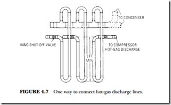
• The compressor hot-gas discharge lines should be connected as shown in Figure 4.7.
• The maximum length of the risers to the horizontal manifold should not exceed 6 feet.
• The manifold size should be at least equal to the size of the common hot-gas line to the evaporative condenser.
• If water-cooled condensers are interconnected, the hot-gas manifolds should be at least equal to the size of the discharge of the largest compressor.
• If evaporative condensers are interconnected, a single gas line should be run to the evaporative condensers, and the same type of manifold provided at the compressors should be installed.
• Always stagger and install the piping at the condensers.
• When the condensers are above the compressors, install a loop with a minimum depth of 3 feet in the hot-gas main line.
• Install a hand shutoff valve in the hot-gas line at each compressor.
Water Valves
The water-regulating valve is the control used with water-cooled condensers. When installing water valves, the following should be observed:
• The condenser water for interconnected compressor condensers should be applied from a common water line.
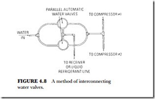
• Single automatic water valves or multiple valves in parallel (Figure 4.8) should be installed in the common water line.
• Pressure-control tubing from the water valves should be connected to a common line, which in turn should be connected to one of the receivers or to the common liquid line.
Multiple-Unit Installation
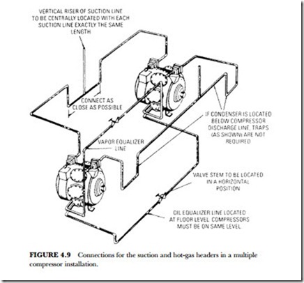
Multiple compressors operating in parallel must be carefully piped to ensure proper operation. The suc- tion piping at parallel compressors should be designed so that all compressors run at the same suction pres- sure and oil is returned in equal proportions to the running compressors. All suction lines should be brought into a common suction header in order to return the oil to each crankcase as uniformly as possible.
The suction header should be run above the level of the compressor suction inlets so that oil can drain into the compressors by gravity. The header should not be below the compressor suction inlets because it can become an oil trap. Branch suction lines to the compressors should be taken off from the side of the header. Care should be taken to make sure that the return mains from the evaporators are not connected into the suction header so as to form crosses with the branch suction lines to the compressors. The suction header should be run full size along its entire length. The horizontal takeoffs to the various compressors should be the same size as the suction header. No reduction should be made in the branch suction lines to the compressors until the vertical drop is reached.
Figure 4.9 shows the suction and hot-gas header arrangements for two compressors operating in parallel. Takeoffs to each compressor from the common suction header should be horizontal and from the side to ensure equal distribution of oil and prevent accumulating liquid refrigerant in an idle compressor in case of slop-over.
Piping Insulation
Insulation is required for refrigeration piping to prevent moisture condensation and prevent heat gain from the surrounding air. The desirable properties of insulation are that it should have a low coefficient of heat transmission, be easy to apply, have a high degree of permanency, and provide protection against air and moisture infiltration. Finally, it should have a reasonable installation cost.
The type and thickness of insulation used depends on the temperature difference between the surface of the pipe and the surrounding air and also on the relative humidity of the air. It should be clearly understood that although a system is designed to operate at a high suction temperature, it is quite difficult to prevent colder temperatures occurring from time to time. This may be due to a carrying over of some liquid from the evaporator or the operation of an evaporator pressure valve. Interchangers are preferable to insulation in this case.
One of the safest pipe insulations available is molded cork or rock cork of the proper thickness. Hair-felt insulation may be used, but great care must be taken to have it properly sealed. For temperatures above 40 degrees F, wool felt or a similar insulation may be used, but here again, success depends on the proper seal against air and moisture infiltration.
Liquid refrigerant lines carry much higher-temperature refrigerant than suction lines; and if this temper- ature is above the temperature of the space through which they pass, no insulation is usually necessary. However, if there is danger of the liquid lines going below the surrounding air temperatures and causing condensation, they should be insulated when condensation will be objectionable. If they must unavoidably pass through highly heated spaces, such as those adjacent to steam pipes, through boiler rooms, etc., then the liquid lines should also be insulated to ensure a solid column of liquid to the expansion valve.
There were four types of insulation in use before the discovery of modern insulation materials. Those you may encounter that were in general use for refrigerator piping, are cork, rock cork, wool felt, and hair felt.
Cork Insulation
Cork pipe covering is prepared by pressing dried and granulated cork in metal molds. The natural resins in the cork bind the entire mass into its new shape. In the case of the cheaper cork, an artificial binder is used. The cork may be molded to fit pipe and fittings, or it may be made into flat boards of varying sizes and thickness. Cork has a low thermal conductivity. The natural binder in the material itself makes cork highly water resistant, and its structure ensures a low capillarity. It can be made practically impervious to water by surfacing with odorless asphalt.
All fittings in the piping, as well as the pipe itself, should be thoroughly insulated to prevent heat gain in order to protect the pipe insulation from moisture infiltration and deterioration and eliminate condensation problems. Molded cork covering made especially for this purpose is available for all common types of fit- tings. Each covering should be the same in every respect as the pipe insulation, with the exception of the shape, and should be formed so that it joins to the pipe insulation with a break. Typical cork fitting covers are furnished in three standard thicknesses for ice water, brine, and special brine.
To secure maximum efficiency and long life from cork covering, it must be correctly applied and serviced as well as properly selected. Hence, it is essential that the manufacturer’s recommendations and instructions be followed in detail. The following general information is a summary of the data.
All pipelines should be thoroughly cleaned, dried, and free from all leaks. It is also advisable to paint the piping with waterproof paint before applying the insulation, although this is not recommended by all man- ufacturers. All joints should be sealed with waterproof cement when applied. Fitting insulation should be ap- plied in substantially the same manner, with the addition of a mixture of hot crude paraffin and granulated cork used to fill the space between the fittings, as shown in Figure 4.4.
Rock-Cork Insulation
Rock-cork insulation is manufactured commercially by molding a mixture of rock wool and a waterproof binder into any shape or thickness desired. The rock wool is made from limestone melted at about 3,000 de- grees F and then blown into fibers by high-pressure steam. It is mixed with an asphalt binder and molded into the various commercial forms. The heat conductivity is about the same as cork, and the installed price may be less. Because of its mineral composition, it is odorless, vermin-proof, and free from decay. Like cork, it can be made completely waterproof by surfacing with odorless asphaltum. The pipe covering fabricated from rock wool and a binder is premolded in single-layer sections 36 inches long to fit all standard pipe sizes and is usually furnished with a factory-applied waterproof jacket.
When pipelines are insulated with rock-cork covering, the fittings are generally insulated with built-up rock wool impregnated with asphalt. This material is generally supplied in felted form, having a nominal thickness of about 1 inch and a width of about 18 inches. It can be readily adapted to any type of fitting and is efficient as an insulator when properly applied.
Before applying the formed rock-cork insulation it is first necessary to thoroughly clean and dry the pip- ing and then paint it with waterproof asphalt paint. The straight lengths of piping are next covered with the insulation, which has the two longitudinal joints and one end joint of each section coated with plastic ce- ment. The sections are butted tightly together with the longitudinal joints at the top and bottom and tem- porarily held in place by staples. The plastic cement should coat that part of the exterior area of each sec- tion to be covered by the waterproof lap and the lap should be pressed smoothly into it. The end joints should be sealed with a waterproof fabric embedded in a coat of the plastic cement. Each section should then be secured permanently in place with three to six loops of copper-plated annealed steel wire.
Wool-Felt Insulation
Wool felt is a relatively inexpensive type of pipe insulation and is made up of successive layers of water- proof wool felt that are indented in the manufacturing process to form air spaces. The inner layer is a wa- terproof asphalt-saturated felt, while the outside layer is an integral waterproof jacket. This insulating ma- terial is satisfactory when it can be kept air- and moisture-tight. If air is allowed to penetrate, condensation will take place in the wool felt, and it will quickly deteriorate. Thus, it is advisable to use it only where tem- peratures above 40 degrees F are encountered and when it is perfectly sealed. Under all conditions, it should carry the manufacturer’s guarantee for the duty that it is to perform.
After all the piping is thoroughly cleaned and dried, the sectional covering is usually applied directly to the pipe with the outer layer slipped back and turned so that all joints are staggered. The joints should be sealed with plastic cement, and the flap of the waterproof jacket should be sealed in place with the same ma- terial. Staples and copper-clad steel wire should be provided to permanently hold the insulation in place, and then the circular joints should be covered with at least two layers of waterproof tape to which plastic ce- ment is applied.
Pipe fittings should be insulated with at least two layers of hair felt (Figure 4.6) built up to the thickness of the pipe covering; but before the felt is placed around the fittings, the exposed ends of the pipe insulation should be coated with plastic cement.
After the felt is in place, two layers of waterproof tape and plastic cement should be applied for protec- tion from moisture infiltration.
Insulation of this type is designed for installation in buildings where it will be normally protected against outside weather conditions. When outside pipes are to be insulated, one of the better types of pipe covering should be used. In all cases, the manufacturer’s recommendations should be followed as to the application.
Hair-Felt Insulation
Hair-felt insulation is usually made from pure cattle hair that has been especially prepared and cleaned. It is a very good insulator against heat, having a low thermal conductivity. Its installed cost is somewhat lower than cork; but it is more difficult to install and seal properly, and hence its use must be considered a hazard with average workmanship. Prior to installation, the piping should be cleaned and dried and then prepared by applying a thickness of waterproof paper or tape wound spirally, over which the hair felt of approximately 1-inch thickness is spirally wound for the desired length of pipe. It is then tightly bound with jute twine, wrapped with a sealing tape to make it entirely airtight, and finally painted with waterproof paint. If more than one thickness of hair felt is desired, it should be built up in layers with tar paper between. When it is necessary to make joints around fittings, the termination of the hair felt should be tapered down with sealing tape, and the insulation applied to the fittings should overlap this taper, thus ensuring a permanently tight fit.
The important point to remember is that this type of insulation must be carefully sealed against any air or moisture infiltration, and even then difficulties may occur after it has been installed. At any point where
air infiltration (or “breathing,” as it is called) is permitted to occur, condensation will start and travel great distances along the pipe, even undermining the insulation that is properly sealed.
There are several other types of pipe insulation available, but they are not used extensively. These include various types of wrapped and felt insulation. Whatever insulation is used, it should be critically examined to see whether it will provide the protection and permanency required of it; otherwise, it should never be considered. Although all refrigerant piping, joints, and fittings should be covered, it is not advisable to do so until the system has been thoroughly leak-tested and operated for a time.
Pressure drop in the various parts of commercial refrigeration systems due to pipe friction and proper dimensioning to obtain the best operating results are important considerations when equipment is installed.
By careful observation of the foregoing detailed description of refrigeration piping and methods of installation, the piping problem will be greatly simplified and result in proper system operation.
