Pipework supports
Currently three types of supports are used: the tubing saddle for smaller diameter tubing; a more elaborate assembly such as Hydra-zorb for larger diameter tubing; and the Munsen ring for iron and steel pipework, which obviously requires a stronger type of support structure (Figure 69).
Pipework must be well supported. For soft drawn copper tubing, the number of saddles used will depend upon the length of tubing run. For long runs the suction and liquid lines should be supported at intervals not exceeding 30 suction line tube diameters.
Hydra-zorb is ideal for larger hard drawn copper tubing and multiple installations. It consists of a metal wall mounted channel into which resilient tube mounting blocks and clamps are inserted.
The Munsen ring is basically a split clamp, which is usually cemented into the wall.
Soft drawn copper tubing supported by saddles brings both suction and liquid lines into close proximity. The tubing can be easily formed to touch and make thermal contact, thus creating heat exchange. The effect is to subcool the liquid refrigerant passing to the expansion valve and superheat the vapour returning to the compressor, which improves the system efficiency.
The other two types of support do not allow this heat exchange. Therefore for those types the tubing should be insulated where there is a possibility of frost or condensation forming.
Isolating valves and controls should be installed in the pipework so as to provide easy access for maintenance or replacement.
Pipework should not obstruct the view of the crankcase oil sight glass. It should also be routed to avoid motor compressor end plates and terminal covers, and the drive belts and motors of open-type units.
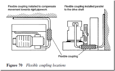
When compressors are resiliently mounted it is advisable to install a flexible coupling (vibration eliminator) between the compressor and the pipework to compensate for movement when the compressor stops or starts. This is common with hermetic and semi-hermetic motor compressors. With open- type units this may not be necessary, but if a flexible coupling is used it should be installed parallel to the compressor drive shaft. These couplings are illustrated in Figure 70.

