Pipe Fitting Wrenches
The numerous wrenches used in pipe fitting may be listed as follows:
• Monkey wrench
• Pipe wrench
• Stillson wrench
• Chain wrench
• Strap wrench
• Open wrench
The important point to remember in pipe fitting is to select a suitable wrench for the job at hand. Each of the aforementioned wrenches is designed for one or more specific tasks. No wrench is suitable for every task encountered in pipe fitting.
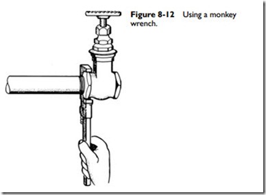
A monkey wrench has smooth parallel jaws that are especially adapted for hexagonal valves and fittings (see Figure 8-12). Not only does it fit better on the part to be turned, it also does not have the crushing effect of a pipe wrench.
The operating principle of a pipe wrench is simple. The harder you pull, the tighter it squeezes the pipe. The pipe wrench was designed for use on pipe and screw fittings only. On parallel-sided objects, its efficiency is not up to that of a monkey wrench, and its squeezing action can do a great deal of damage.
Many inexperienced fitters have learned from experience that using a pipe wrench too large for the job can cause the fitting to
stretch or crack. The result is a leaking joint that will require a new fitting to remedy the damage.
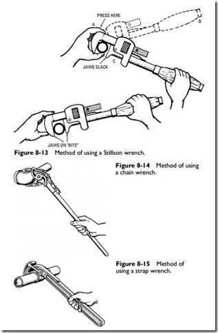
A Stillson wrench has serrated teeth jaws that enable it to grip a pipe or round surface in order to turn it against considerable resis- tance. The correct method for using a Stillson wrench is illustrated in Figure 8-13. Adjust the wrench so that the jaws will take hold of the pipe at about the middle part of the jaws. To support the wrench and prevent unnecessary lost motion when the wrench engages the pipe, hold the jaw at A, with the left hand pressing it against the pipe. At the beginning of the turning stroke B, with the jaw held firmly against the pipe with the left hand, the wrench will at once bite or take hold of the pipe with only the lost motion necessary to bring jaw C in contact with the pipe.
Figure 8-14 shows a chain wrench (or pipe tongs) and the method in which it is used. Although they are made for small sizes up, they are generally used for 6-inch pipe and larger.
A strap wrench (see Figure 8-15) is used when working with plated or polished-finish piping in order not to mar the surface. It also comes in handy in tight places where you cannot insert a Stillson wrench.
Open-end wrenches (see Figure 8-16) are used for making up flange couplings. The right size should be used in order to prevent wearing of the bolt heads or slippage that can cause bruised knuckles.
Pipe Vise
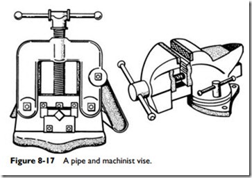
Either a pipe vise or a machinist vise (see Figure 8-17) can be used in pipe fitting. The pipe vise is used for pipe only. The machinist vise, on the other hand, has square jaws or a combination of square and gripper jaws, making it suitable for pipe as well as other work.
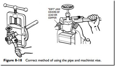
Several precautions should be taken when using a pipe vise. It exerts a powerful force at the jaws, which in some cases can do dam- age to the pipe. That is why experienced fitters never put a valve or fitting into a vise when making up a joint at the bench. There is too much danger of distorting the part by oversqueezing it or of putting the working parts of a valve out of line. The correct and incorrect methods of connecting a valve to a pipe are illustrated in Figure 8-18. Always hold a valve between lead- or copper-covered machinist vise jaws while unscrewing the bonnet (see Figure 8-18).
Installation Methods
Pipe fitting may be defined as the operations that must be per- formed in installing a pipe system made up of pipe and fittings. These pipe fitting operations can be listed as follows:
1. Cutting.
2. Threading.
3. Reaming.
4. Cleaning.
5. Tapping.
6. Bending.
7. Assembling.
8. Making up.
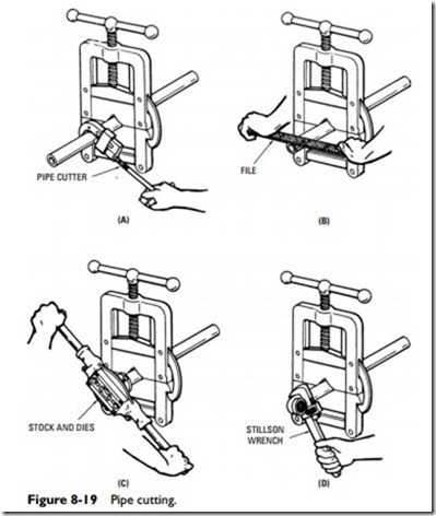
Figure 8-19 illustrates the principal operations in pipe fitting. After being marked to length by nicking with a file, the pipe is put in a vise and cut with a pipe cutter (or hacksaw) as shown in Figure 8-19A. Any external enlargement is removed with a metal file (see Figure 8-19B). The thread is next cut with stock and dies as in Figure 8-19C. After carefully cleaning the thread with a hard toothbrush and applying red lead or pipe cement to the freshly cut thread, the joint is made up with a Stillson wrench (see Figure 8-19D).
Pipe Cutting
Pipe is manufactured in different lengths varying from 12 to 22 feet. Accordingly, it must be cut to required length for the pipe
installation. This may be done with either a hacksaw or a pipe cut- ter. The latter method is generally quicker and more convenient.
When a length of pipe is being cut or threaded, it is held firmly in a pipe vise. The pipe vise should be adjusted just tight enough to prevent the pipe from slipping, but not so tight as to cause the jaw teeth to unduly dig into the pipe.
A pipe cutter is a tool usually consisting of a hoop-shaped frame on whose stem a slide can be moved by a screw. On the side and frame, several cutting dies on wheels are mounted. In cutting, the pipe cutter is placed around the pipe so that the wheels contact the pipe. The tool is rotated around the pipe, tightening up with the screw stem each revolution until the pipe is cut.
The operating principles of a three-wheel cutter and a combined wheel and roller cutter are illustrated in Figure 8-20A. The cuts show the comparative movements necessary with the two types of cutters to perform their functions. The three-wheel cutter requires only a small arc of movement and is recommended for cutting pipe in inaccessible locations. The wheel cutter has a greater range than the roller cutter and is therefore preferred for general use.
The major disadvantage of a pipe cutter is that it does not cut but crushes the metal of the pipe, leaving a shoulder on the outside and a burr on the inside. This does not apply to the knife-type pipe cutter designed to actually cut (not crush) the pipe.
Figure 8-20B shows the appearance of pipe when cut by a hack- saw or knife cutter and when cut by a wheel pipe cutter. When the latter is used, the external enlargement must be removed by a file and the internal burr by a pipe reamer.
