Extension or Joining Fittings
Nipples, locknuts, couplings, offsets, joints, and unions are all examples of extension or joining fittings. With the possible excep- tion of an offset, these fittings are designed to join and extend (but not change the direction of) a length of pipe. An offset is used to reposition a length of piping so that it is parallel but not in alignment with another section of its length. The offset itself constitutes a change of direction; however, its function is to create a piping run parallel but not in alignment with the rest of its length.
Nipples
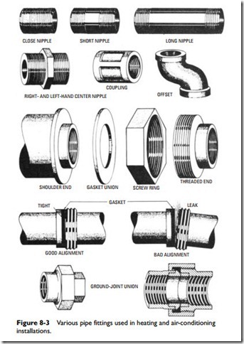
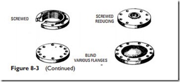
Nipples are classified as close, short, or long (see Figure 8-3).
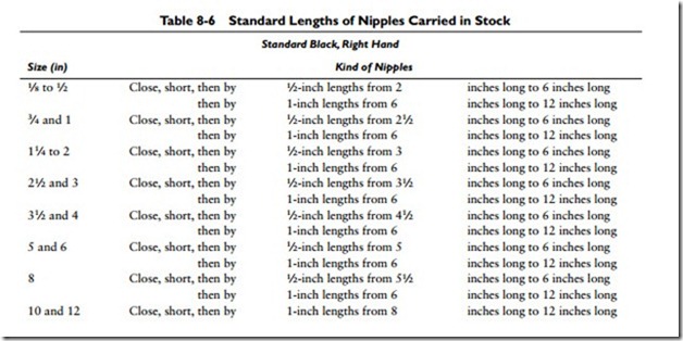
Standard lengths of nipples are listed in Table 8-6. The length of close nipples varies with the pipe size, it being determined by the length of thread necessary to make a satisfactory joint. There is one length of
short nipple for each size of pipe. Long nipples are made in many lengths up to 12 inches. Anything over 12 inches is known as cut pipe.
Locknuts
Locknuts are commonly used on long screw nipples that have couplings (see Figure 8-3). A recessed or grooved end on the locknut fitting is used to hold packing when a particularly tight joint is required. If at all possible, a union is preferred to a locknut because a much tighter joint is obtained.
The standard length for all sizes of locknut (or tank nipples) is 6 inches. They are made from standard-weight pipe threaded (for lock- nut) 4 inches long on one end and with regular pipe thread on the other. Tank nipples longer than 6 inches are made-to-order only.
Couplings
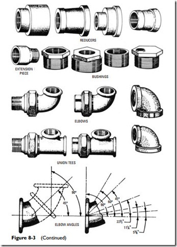
A coupling is a pipe fitting used to couple or connect two lengths of pipe. They are available in numerous sizes and types. The standard coupling (see Figure 8-3) is threaded with right-hand threads. Others are available with both right-hand and left-hand threads. The extension piece coupling illustrated in Figure 8-3 has a male thread at one end. Couplings used as reducers (see Figure 8-3) are also common.
Offsets
An offset fitting (see Figure 8-3) is used when it is necessary to pass the pipeline around an obstruction that blocks its path. The new path will be parallel to the old one, but not aligned with it.
Joints
A joint (also referred to as an expansion joint or bend) is a pipe fitting designed to accommodate the linear expansion and contraction of the pipe metal caused by the temperature differences between the water or steam inside the pipe and the air on the outside of it. The
amount of expansion or contraction at different temperatures for a variety of metals used in steam pipes is listed in Table 8-7.
Unions
A union is another form of extension fitting used to join two pipes.
The two most common types of unions are (1) the ground-joint union and (2) the plain or gasket union.
A ground-joint union (see Figure 8-3) consists of a composition ring pressing against iron or both contact surfaces of composition. A joint using a ground-joint union is characterized by spherical contact. Because no gasket is used, perfect alignment of the two pipes is not as important in making up the joint as it is when a plain or gasket union is used.
A disassembled plain or gasket union fitting is shown in Figure 8-3. It consists of three basic parts and a gasket. In assembling, the gas- ket (A) is placed over the projection on the shoulder so that it is in contact with its surface (B). The ring is slipped over the shoulder end and the threaded end placed in position so that the flat surface (C) of the threaded end presses against the gasket. The ring is then screwed firmly into the threaded end. Since the shoulder on the shoulder end cannot back off the ring, the two ends are pressed firmly together against the gasket by the ring, thus securing a tight joint.
The limitations of the plain or gasket union are also illustrated in Figure 8-3. The alignment must be good to secure a tight joint. In the illustration, the ring section is omitted for clearness. If both ends are in line and firmly pressed together against the gasket by the ring, the gasket will bear evenly over the entire contact surface and the joint will be tight. If the two ends are out of alignment when the ring is screwed tight, it will bring great pressure on the gasket at point A, and the surfaces will not come together at the opposite point B, thus causing a leak.
