Heating Relays/Time-Delay Relays
In air-conditioning installations, a time-delay relay is often installed in the control circuit to provide protection for the compressor and contactor. This device is activated or deactivated by the room thermostat. In operation, it causes a time delay between turning down the thermostat setting and the start of the compressor unit of approximately 20 to 45 seconds (depending on the manufacturer). On the shutoff cycle at the thermostat, the same delay occurs. This control prevents rapid short cycles from occurring.
A time-delay relay is essentially a switching relay that contains a small heater wound around a bimetal element. The relay heater is
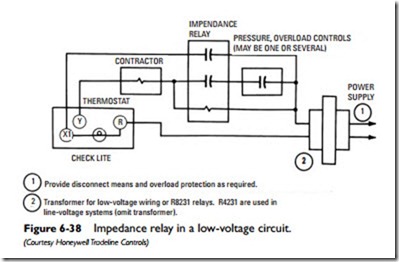
1 Provide disconnect means and overload protection as required.
2 Transformer for low-voltage wiring or R8231 relays. R4231 are used in line-voltage systems (omit transformer).
energized through the cooling contacts of the thermostat and heats the bimetal element. After a time delay of approximately 20 to 45 seconds, the heated bimetal element bends to provide the switching force. In other words, it closes a set of snap-action contacts, thereby completing the circuit through the starter or contactor coil required to start the compressor. The relay may be wired to provide a delay in breaking the circuit after the thermostat is satisfied.
The time-delay relay shown in Figure 6-39 is used with a two- wire low-voltage thermostat (and remote-mounted thermostat) to provide a time delay between stages for electric heaters in furnace ducts. Each relay can control up to 6000 watts at 240 volts AC. One relay is required per stage or time increment. This particular model provides a delay of approximately 75 seconds between the on cycles of consecutive stages. The sequencing of heating loads is permitted by auxiliary contacts.
Because of the dual nature of their function, time-delay relays are also referred to as time-delay switches, thermal switching relays, ther- mal time-delay relays, thermal relays, and heating relays. Other examples of time-delay/heating relays are shown in Figures 6-40 and 6-41.

