FUEL TANK AND LINE
The fuel tank and line must be installed in accordance with the requirements of the Underwriters’ Laboratories and any local codes and regulations. Local codes and regulations take precedence over national standards. Additional information can be obtained from “Installation of Oil Burning Equipment 1972” (NFPA No. 31), a publication of the National Fire Protection Association. Use only an approved tank and line for the installation.
A one-pipe system is recommended for an oil tank installation when the following conditions are present:
1. Tank is installed in the basement or similar location and/ or below the oil pump inlet port.
2. Vacuum at pump does not exceed 2 inches.
A two-pipe (return line) system is recommended for a tank in stallation when the following conditions exist:
1. Tank is located outside and/or below the oil pump inlet port.
2. Vacuum at pump does not exceed 10 inches.
Use a two-stage pump for installations having especially long lines or high lifts if the vacuum at the inlet port does not exceed 20 inches.
A shutoff valve should be installed in the suction line close to the oil burner. This valve enables the operator to disconnect the line without draining it. Do not place a shutoff valve in the return line. Closing a shutoff valve on the return line while the oil burner is operating could damage the pump. All joints in the fuel line should be sealed with a suitable oil piping compound.
OIL FILTER
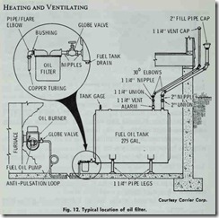
An oil filter should be included in the fuel line inside the build ing and as close to the fuel tank as possible (Fig. 12). One filter is adequate on oil burners using more than 1.00 gph.
Change the filter cartridge at least. once a year. The filter body should be thoroughly cleaned before installing a new cartridge.
PRIMING THE FUEL PUMP
On occasion, the oil burner may fail to pump oil. When this occurs, check the oil supply line to the furnace for leaks. If there are no leaks, it may be necessary to prime the fuel pump. Pumps are self priming for single-stage, two-pipe systems and two-stage pumps. A single-stage pump (one-pipe system) should be primed as follows:
I. Tum off the electrical power supply to the unit.
2. Read and follow the priming instructions provided by the manufacturer.
Prime the pump until the oil is free from bubbles.
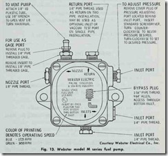
When a new pump fails to prim e, it ma y be due to dry pump conditions. This can be corrected by rem oving th e ve nt plug and filling the pressur e cavity slowl y so that th e fuel oil ‘wet s” th e gears (Fig. 13).
Table 5. Maximum recommended pressures.
|
Bonnet Capacity (1000 Btuh) |
Firing Rate (gph) |
Standard No:n:le Size |
Pump Pressure (psig) |
|
85 |
.76 |
.75 |
103 |
|
100 |
.90 |
.90 |
100 |
|
125 |
1.12 |
1.10 |
104 |
|
150 |
1.35 |
1.35 |
100 |
|
200 |
1.80 |
1.75 |
112 |
|
250 |
2.25 |
2.25 |
100 |
|
335 |
3.00 |
1.50 |
100 |
Courtesy Carrier Corp.
ADJUSTING OIL PUMP PRESSURE
The oil pressure regulator on the fuel pump is generally fac tory set to give nozzle oil pressures of 100 psig. The firing rate is indicated on the nameplate, and can be obtained with standard nozzles by adjusting the pump pressures as follows (Fig. 13).
1. Turn the adjusting screw clockwise to increase pressure.
2. Turn the adjusting screw counterclockwise to decrease pressure.
3. Never exceed the pressures indicated in Table 5.
STARTING THE BURNER
The procedure for starting an oil burner may be summarized as follows:
1. Open all warm air registers.
2. Check to be sure all return air grilles are unobstructed.
3. Open the valve on the oil supply line.
4. Reset the burner primary relay.
5. Set the thermostat above the room temperature.
6. Turn on the electric supply to the unit by setting the main electrical switch to the ON position.
7. Change the room thermostat setting to the desired temper ature.
The oil burner should start after the electric power has been switched on (Step 6). There is no pilot to light as is the case with gas-fired appliances. The spark for ignition is provided automati cally on demand from the room thermostat.
Allow the burner to operate at least 10 minutes before making any final adjustments. Whenever possible use instruments to adjust the fire.
COMBUSTION TESTING AND ADJUSTMENTS
The instruments recommended for combustion testing and ad justments are:
1. Draft gauge,
Figure 6. Smoke scale.
|
BACHARACH SMOKE SCALE NO. |
RATING |
SOOTING PRODUCED |
|
1 |
EXCELLENT |
EXTREMELY LIGHT IF AT ALL |
|
2 |
GOOD |
SLIGHT SOOTING WHICH WILL NOT INCR EASE STACK TEMPERATURE APPRECIABLY |
|
3 |
FAIR |
MAY BE SOME SOOTING BUT WILL RARELY REQUIRE CLEANING MORE THAN ONCE A YEAR |
|
4 |
POOR |
BORDERLINE CONDITION SOME UNITS WILL REQUIRE CLEANING MORE THAN ONCE A YEAR |
|
5 |
VERY POOR |
SOOT RAPIDLY AND HEAVILY |
Courtesy Bacharach Instrument Co.
2. Smoke tester,
3. Carbon dioxide tester,
4. 200/1000°F. stack thermometer,
5. 0I 150-psig pressure gauge,
6. 0/30-inch mercury vacuum gauge.
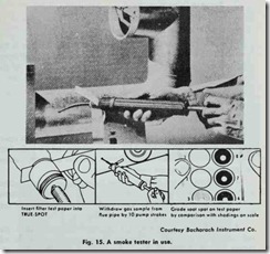
Smoky combustion indicates poor burner performance. The amount of smoke in the flue gas can be measured with a smoke tester (Fig. 14). The tube of the smoke tester is inserted through a ¥s inch hole drilled in the flue pipe, and the test is run as shown in Fig. 15. Any smoke in the air drawn into the smoke tester will register on a filter paper inserted in the device. The results are in terpreted according to the smoke scale in Table 6.
One of the most common causes of smoky combustion is soot formation on the heating surfaces. This is easily corrected by clean ing. Other possible causes of smoky combustion include:
1. Insufficient draft,
2. Poor fuel supply,
3. Fuel pump malfunctioning,
4. Defective firebox,
5. Incorrectly adjusted draft regulator,
Defective oil burner nozzle,
6. Wrong size oil burner nozzle,
8. Improper fan delivery,
9. Excessive air leaks in boiler or furnace,
10. Unsuitable fuel-air ratio.
Net stack temperatures in excess of 700°F for conversion units and 500°F for packaged units are considered abnormally high. The net stack temperature is the difference between the temperature of the flue gases inside the pipe and the room air temperature outside. For example, if the flue gas temperature is 600°F and the room temperature is 75 °F, then the net stack temperature is 525°F (600°F -75°F = 525°F).
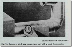
A 200/ 1000°F stack thermometer is used to measure the flue gas temperature. The thermometer stem is inserted through a hole drilled in the flue pipe (Fig. 16). A high stack temperature may be caused by any of the following:
1. Undersized furnace.
2. Defective combustion chamber.
3. Incorrectly sized combustion chamber.
4. Lack of sufficient baffling.
5. Dirty heating surfaces.
6. Excessive draft.
7. Boiler or furnace overfired.
8. Unit unsuited to automatic firing.
9. Draft regulator improperly adjusted.
When the carbon dioxide (CO:!) content of the flue gas is too low (less than 8% ), heat is lost up the chimney and the unit oper ates inefficiently. This condition is usually caused by one of the following:
1. Underfiring the combustion chamber.
2. Burner nozzle is too small.
3. Air leakage into the furnace or boiler.
When the carbon dioxide content is too high, the furnace oper ation is generally characterized by excess smoke and/or pulsations and other noises. A high carbon dioxide content is usually caused by insufficient draft or an overfired burner.
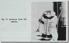
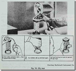
The carbon dioxide reading is also taken through a hole drilled in the flue pipe with a CO:! indicator (Fig. 17). The C02 indicator is used as shown in Fig. 18. The results are indicated by a test liquid on a scale calibrated in percent C02 .
A correct draft is essential for efficient burner operation. In sufficient draft can make it almost impossible to adjust the oil burner for its highest efficiency. Excessive draft can reduce the percentage of carbon dioxide in the flue gases and increase the stack temperature.
For the most efficient operating characteristics, the overfire draft generally should be not less than 0.02 inches wg. Smoke and odor often occur when the overfire draft falls below 0.02 inches wg.
It may be necessary to adjust the barometric draft regulator to obtain the correct overfire draft. If it is not possible to adjust the overfire draft for a minus 0.0 I to 0.02 inches wg., install a me chanical draft inducer between the chimney and the barometric draft regulator.
The primary air band should be adjusted to a 0 + smoke or until a hard clean flame is visible. A clean flame is preferred to
one with high carbon dioxide. Adjust the overfire draft for a minus 0.01 to a minus 0.02 inch es wg. An excessive overfire draft condition will cause high stack temperature and inefficient operation. A too low or positive draft over the fire will usually cause the flue gases and fumes to seep into the space upon start up or shutdown.
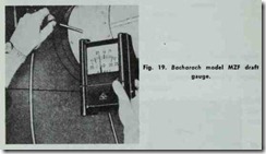
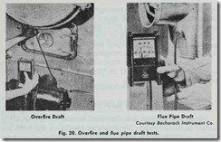
The flue pipe draft in most residential oil burners is between 0.04 and 0.06 inches water. This is sufficient to maintain a draft of 0.02 inches in the firebox.The furnace or boiler draft is measured with a draft gauge as shown in Fig. 19. A hole is drilled in either the fire door (overfire draft measurement) or flue pipe (flue pipe draft measurement) and the unit is run for approximately 5 minutes. The draft tube is then inserted into the test hole and the gauge is read (Fig. 20).
BLOWERS AND MOTORS
Both direct-drive and belt-driven blowers are used with oil fired furnaces. These blowers and motors are identical to those used in gas-fired furnaces. Read the section BLOWERS AND MO TORS in Chapter 11 (GAS-FIRED FURNACES) for additional information.
AIR DELIVERY AND BLOWER ADJUSTMENT
It is sometimes necessary to adjust the blower speed to produce a temperature rise through the furnace that falls within the limits stamped on the furnace nameplate. Blower adjustment procedures are described in Chapter 11 (GAS-FIRED FURNACES).
