Oil-Fired Furnaces
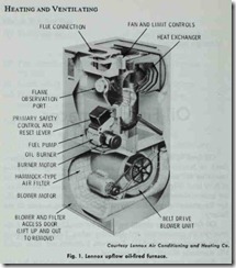
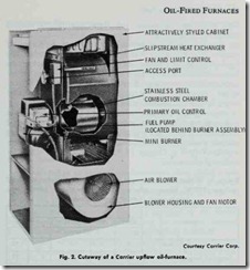
Oil-fired furnaces are available in upflow, downflow (counter flow), or horizontal flow models and in a wide range of heating capacities for installations in attics, basements, closet spaces, or at floor level (Figs. 1 and 2). The furnace, oil burner, and controls are generally available from the manufacturer as a complete pack age for residential installations. All internal wiring is done at the factory.
Oil-fired furnaces should be listed by the Underwriters’ Lab oratories for construction and operating safety. Furnaces approved by the agency are marked UL Approved. Furnaces not made under UL standards should not be installed.
Another source of information concerning standards for oil fired furnaces is the publication “Installation of Oil Burning Equip ment 1972” (NFPA No. 31) from the National Fire Protection Association. See also “American Standard Performance Require ments for Oil-Powered Central Furnaces” (ANSI Z91.1-1972), a publication of the American National Standards Institute.
PLANNING SUGGESTIONS
The first step in planning a heating system is to calculate .the maximum heat loss for the structure. This should be done in ac cordance with procedures described in the manuals of the National Warm Air Heating and Air Conditioning Association or by a comparable method. This is very important, because the data will be used to determine the size (capacity) of the furnace selected for the installation.
Location and Clearance
An oil-fired warm-air furnace should be located as near as possible to the center of the heat distribution system and chimney. A centralized location for the furnace usually results in the best operating characteristics, because long supply ducts and the heat loss associated with them are eliminated. The furnace should be installed as close as possible to the chimney to reduce the hori zontal run of flue pipe.
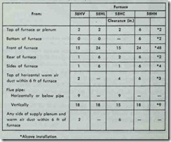
An oil-fired furnace should be located a safe distance from any combustible material. Observe the minimum clearances suggested by the manufacturer for the furnace except where they may come into conflict with local codes and regulations (Table 1). Local standards always take precedence over the manufacturer’s specifi cations or national standards. Where there are no local standards specifying clearances, use those listed in “Installation of Oil Burn ing Equipment 1972” (NFPA No. 31-1972). Contents of the 1972 edition have been approved by the American National Standards Institute (ANSI).
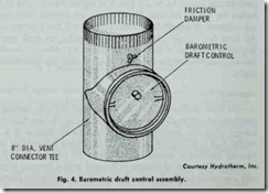
Allow access for servicing the furnace and oil burner. Sufficient clearance should also be provided for access to the barometric draft control assembly.
Installation Recommendations
The installation of an oil-fired furnace should comply with all local codes and regulations, and “Installation of Oil Burning Equipment 1972”.
New furnaces for residential installations are shipped preas sembled from the factory with all internal wiring completed. The fuel tank must be installed and the fuel line connected to the furnace by the installer. The electrical service from the line voltage main, and the low-voltage thermostat will also have to be con nected. Directions for making these connections are included in the furnace manufacturer’s installation literature.
Make certain you have familiarized yourself with all local codes and regulations which govern the installation of an oil-fired furnace. Local codes and regulations always take precedence over national standards. Read the section INSTALLATION RECOM MENDATIONS in Chapter 11 (GAS-FIRED FURNACES) for additional information.
Table 1. Minimum clearances specified for Carrier oil-fired upflow (SSHV), loboy upflow (58HL), downflow (SSHC), and horizontal (SSHH) furnace models.
Duct Connections
Detailed information concerning the installation of an air duct system is contained in the following two publications of the National Fire Protection Association:
1. “Installation of Air Conditioning and Ventilating Systems of Other Than Residence Type” (NFPA No. 90A).
2. “Residence Type Warm Air Heating and Air Conditioning Systems” (NFPA No. 90B).
Additional information about duct connections can be found in Chapter 7, Volume 2 (DUCTS AND DUCT SYSTEMS). The specific recommendations concerning furnace duct connections and the air distribution ducts contained in Chapter 11 (GAS-FIRED FURNACES) also apply to gas-fired furnaces.
Electric Wiring
A !ways follow all national and local codes when wiring a unit. The local code should take precedence when there is a conflict between the two. If there is no local electrical code in force, do all wiring in accordance with the National Electric Code.
Closely follow the wiring diagrams provided by the furnace
manufacturer and those who manufacture the automatic controls. Failure to do this may result in losing the factory warranty.
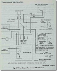
A typical wiring diagram for an oil-fired furnace is shown in Fig. 3. The comments made in Chapter 11 (GAS-FIRED FUR NACES) concerning line voltage and control voltage wiring con nections also pertain to the wiring of oil-fired units.
Ventilation and Combustion Air
An oil-fired furnace should be located where a sufficient sup ply of air is available for combustion, proper venting, and the maintenance of suitable ambient temperature. In buildings of exceptionally tight construction, an outside air supply should be introduced for ventilation and combustion purposes.
If the furnace is located in a confined space such as a furnace room, closet, or utility room, the enclosure should be provided with two permanent openings for the passage of the air supply. One opening should be located approximately 6 inches from the top of the enclosure and the other opening approximately 6 inches from the bottom. Each opening should have a free area of at least 1 square inch per 1000 Btu per hour (minimum size 100 square inches) of the total input rating, or one square foot per gallon of oil per hour.
The size of the openings must correspond to the bonnet capacity of the furnace. Furnace manufacturers generally recommend suitable sizes for air openings in their equipment specifications (Table 2).
Air from an attic or a crawl space can also serve as a ventilation and combustion air supply to a confined furnace. Suitable
Table 2. Recommended sizes of ventilation openings for Trane counterflow oil-fired furnace.
|
Bonnet Capacity 1,000 B.T.U./Hr. |
Length ln. |
Height ln. |
|
85 |
24 |
12 |
|
100 |
24 |
12 |
|
125 |
26 |
13 |
openings near (or on) the floor and near (or on) the ceiling must be provided for the passage of the air.
When an oil furnace is installed in an unconfined area such as a full basement, the full amount of air necessary for combustion is generally supplied by infiltration. Only when the construction is exceptionally tight is it necessary to provide openings to the outdoors.
Combustion Draft
An oil-fired furnace requires sufficient draft for the proper burning of oil. The average combustion draft is usually 0.02 inches wg over the fire (the so-called overfire draft), and between
0.04 and 0.06 inches wg draft in the stack (the flue draft) for units having inputs up to 2.0 gph. For higher inputs, 0.06 to 0.08 inches wg will be the rule. These figures are average ones and do not apply to all installations. For example, a XXth Century Zeph Air Low Boy furnace only requires 0.01 inches wg draft over the fire and a flue draft of 0.02 to 0.03 inches wg. A !ways consult the furnace manufacturer’s operating manual first for recommended drafts.
Venting
Oil-fired appliances use the same methods for venting the products of combustion to the outside air as do gas-fired units, except when the venting method is specifically limited to a par ticular fuel (e.g. Type B gas vents). Additional information about venting methods is contained in Chapter 11 (GAS-FIRED FUR NACES). The type of venting to be used with a furnace is gener ally recommended by the manufacturer in the installation literature.
Flue Pipe
Use 24 gauge galvanized flue pipe (or its equivalent) for the flue connection between the furnace and the chimney. The hori zontal run of flue pipe should slope upward at least inch per running foot. The pitch should not exceed 75% of the vertical vent. Locate the unit so that the furnace flue outlet is no more than ten flue pipe diameters from the chimney connection. If the distance is greater, use the next size larger flue pipe.
Insulate the flue pipe when it passes near combustible material. The Underwriters’ Laboratories require that any uninsulated flue pipe be installed with a minimum clearance of 6 inches from any combustible materials.
Draft Regulator
A draft regulator (or barometric draft regulator) is a device designed to maintain a proper draft in an oil-fired furnace by auto matically reducing the chimney draft (i.e. the flue draft) to the desired value (Fig. 4).
Draft regulators are recommended on all installations for each oil-fired appliance connected to a chimney unless the appliance is listed for use without one. ,
Do not use a small draft regulator, because they will not do a satisfactory job. The draft regulator should be installed in the horizontal flue pipe as close as possible to the chimney. When this flue pipe is too short for a satisfactory installation, the draft regulator should be installed in the chimney either above or below the flue pipe entry into the chimney. Some authorities oppose installing the draft regulator in the chimney, but experience has shown that this can be a very satisfactory installation.
