Troubleshooting Electrodes
The gun assembly must be removed from the oil burner in order to inspect the electrodes. The following conditions require electrode replacement:
• Cracks in the electrode coating
• Dull electrode points
• Broken electrodes
Servicing Electrodes
Remove the electrodes by loosening the screw connecting them to the gun assembly. If the electrodes are round and appear worn, use a file to reestablish a good point. Reinstall them in the electrode holder and set the electrode gap at 1⁄2 inch. Set the distance between the center of the nozzle and the tips at 1⁄4 inch.
Broken electrodes or electrodes with cracked ceramic coatings must be replaced with new ones.
Oil Burner Air System
The air system for the average oil burner is generally composed of the air shutter draft tube, the turbulator, and the fan. The draft tube and turbulator have already been shown (see Figures 1-2 and 1-12).
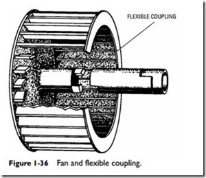
The fan construction consists of a (squirrel cage) series of vanes or blades mounted on the rim of a wheel. These vanes are slanted for- ward in such a manner as to provide the maximum discharge of air. Figure 1-36 shows the construction of a fan and flexible coupling.
The operating principles of the air system are fairly simple. The fan draws air into the fan housing and forces this air through the
draft tube and turbulator and into the combustion chamber. The amount of incoming air can be regulated by adjusting the air shutter. As the air is forced through these vanes, it is given a swirling motion just before it strikes the oil spray. This motion provides a more thorough mixture of the oil and air, resulting in better combustion.
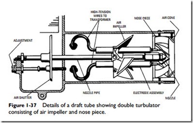
The shape of the turbulator varies in different models, but the purpose is the same: to thoroughly mix the air and oil spray. Figure 1-37 shows a double turbulator consisting of an air impeller and nose piece.


