The Squirrel-Cage Induction Motor
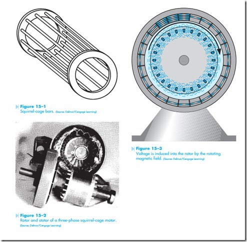
The squirrel-cage induction motor receives its name from the fact that the rotor contains a set of bars that resemble a squirrel cage. If the soft-iron laminations were to be removed from the rotor, it would be seen that the rotor contains a set of metal bars joined together at each end by a metal ring, Figure 15–1. Figure 15–2 shows a complete squirrel-cage rotor and stator winding.
PRINCIPLE OF OPERATION
The squirrel-cage motor is an induction motor. This means that the current flow in the rotor is produced by induced voltage from the rotating magnetic field of the stator. In Figure 15–3, a squirrel-cage rotor is shown inside the stator winding of a three-phase motor. It will be assumed that the motor shown in Figure 15–3 contains four poles per phase, which
produces a synchronous speed of 1,800 RPM (revo- lutions per minute) when the stator is connected to a 60-Hz line. When power is first connected to the stator, the rotor is not turning. The magnetic field of the stator cuts the rotor bars at a rate of 1,800 RPM. Three factors that determine the amount of induced voltage follow:
1. The strength of the magnetic field.
2. The number of turns of wire cut by the magnetic field. (This is sometimes stated as length of conductor.)
3. Speed of the cutting action.
Because the rotor is stationary at this time, maxi- mum voltage is induced into the rotor. The induced voltage causes current to flow through the rotor bars. As current flows through the rotor, a magnetic field is produced around each rotor bar. The magnetic field of the rotor is attracted to the magnetic field of the stator, and the rotor begins to turn in the same direction as the rotating magnetic field.
As the speed of the rotor increases, the rotating magnetic field cuts the rotor bars at a slower rate. For example, assume the rotor has accelerated to a speed of 600 RPM. The synchronous speed of the rotating magnetic field is 1,800 RPM. There- fore, the rotor is being cut at a rate of 1,200 RPM.
(1,800 RPM – 600 RPM = 1,200 RPM). Because the rotor is being cut at a slower rate, less voltage is induced into the rotor. This produces less current flow through the rotor. When the current flow in the rotor is reduced, the current flow in the stator is reduced also.
As the rotor continues to accelerate, the rotating magnetic field cuts the rotor bars at a slower rate. This causes less voltage to be induced into the rotor, and therefore, less current flow in the rotor. Notice that the maximum amount of induced voltage and current occurs when the rotor is not turning at the instant of start. This is the reason that AC induction motors require more current to start than to run.
TORQUE
Torque is the amount of turning or twisting force developed by a motor. It is generally measured in pound-inches or pound-feet depending on the application. Imagine a bar one foot in length attached to the shaft of a motor. A torque of one pound-foot would be the force exerted by applying a pressure of one pound on the end of the bar.
The amount of torque produced by an AC induction motor is determined by three factors. These are:
1. The strength of the magnetic field of the stator.
2. The strength of the magnetic field of the rotor.
3. The phase angle difference between stator and rotor flux.
Notice that one of the factors that determines the amount of torque produced by an induction motor is the strength of the magnetic field of the rotor. An induction motor cannot run at synchronous speed. If the rotor was to accelerate to the speed of the rotating magnetic field, there would be no cutting action of the squirrel- cage bars and, therefore, no current flow in the rotor. If there was no current flow in the rotor, there could be no rotor magnetic field and, therefore, no torque.
When an induction motor is operating with no load connected to it, it will run close to the synchronous speed. For example, a four-pole motor that has a synchronous speed of 1,800 RPM could run at 1,795 RPM at no load. The speed of an AC induction motor is determined by the amount of torque needed. When the motor is operating at no load, it will produce only the amount of torque needed to overcome its own friction and windage losses. This low torque requirement permits the motor to operate at a speed close to that of the rotating magnetic field.
If a load is connected to the motor, it must furnish more torque to operate the load. This causes the motor to slow down. When the motor speed decreases, the rotating magnetic field cuts the rotor bars at a faster rate. This causes more volt- age to be induced in the rotor and, therefore, more current. The increased current flow produces a stronger magnetic field in the rotor, which causes more torque to be produced by the motor. As the current flow increases in the rotor, it causes more current flow to be produced in the stator. This is why motor current will increase as load is added to the motor.
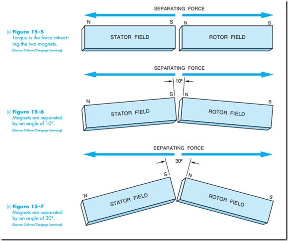
Another factor that determines the amount of torque produced by an induction motor is the phase angle difference between rotor and stator flux. Motor torque is basically the attracting force of two magnetic fields. Imagine two bar magnets representing the magnetic fields of the stator and rotor, Figure 15–4. If the north end of one magnetic is placed close to the south end of the other, they will be attracted to each other, Figure 15–5. Torque can be compared to the amount of force necessary to separate the two magnets. When the magnets are in line with each other, as shown in Figure 15–5, the attraction is strongest and the amount of force necessary to separate them is the greatest. This com- pares to the stator flux and rotor flux being in phase with each other.
Now assume that the two magnets are placed at an angle of 10° to each other, Figure 15–6. The 10-degree angle produces a greater amount of separation between the two magnetic fields. The magnets can now be separated with less force. Now assume that the magnets are placed at a 30° angle to each other, Figure 15–7. The amount of force necessary to separate the two magnets is less than it was at a 10° angle. The greater the angle between the two magnets, the less force required to separate them. This corresponds to the phase angle difference between rotor and stator flux. The greater the phase angle between rotor and stator flux, the less torque that is developed by the motor.


