THE BRUSHLESS EXCITER
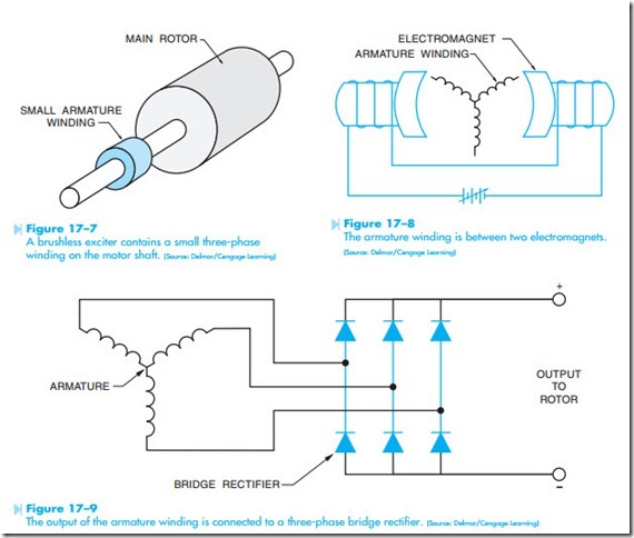
Many large synchronous motors use a brush- less exciter instead of slip rings and brushes. The brushless exciter is constructed by incorporating a small three-phase alternator winding on the shaft of the motor, Figure 17–7. The three-phase winding is placed inside the field of electromagnets, Figure 17–8. A variable source of direct current is used to control the strength of the electromagnets. The amount of voltage induced into the armature winding is determined by three factors:
1. The number of turns of wire in the armature winding.
2. The speed of the armature.
3. The strength of the electromagnets.
Because the amount of DC current that flows through the windings of the electromagnets deter- mines their strength, the output voltage of the three-phase armature can be controlled by the DC excitation current.
The output voltage of the alternator winding is then rectified to direct current with a three-phase bridge rectifier, Figure 17–9. The bridge rectifier and all protective devices such as fuses are mounted on the motor shaft with the armature winding. The output of the bridge rectifier is connected to the
winding of the main rotor. The amount of DC excitation in the rotor of the synchronous motor is now controlled by the amount of DC excitation current supplied to the windings of the electromagnets.
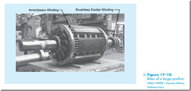
The rotor of a large synchronous motor is shown in Figure 17–10. The amortisseur winding and the brushless exciter winding can be seen in the photo- graph.

