SYNCHRONOUS SPEED
The speed at which the magnetic field rotates is known as the synchronous speed. The synchro- nous speed of a three-phase motor is determined by two factors. These are:
1. The number of stator poles.
2. The frequency of the AC line.
Because 60 Hz is a standard frequency throughout the United States and Canada, the following gives
The magnetic field is concentrated between the poles
STATOR WINDINGS
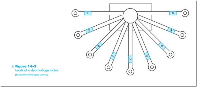
The stator windings of three-phase motors are connected in either a wye or delta. Some stators are designed in such a manner as to be connected in either wye or delta, depending on the operation of is a schematic diagram, and that when connecting a three-phase motor for operation at the proper voltage, the leads will look more like Figure 14–3. This figure illustrates the leads coming out of the terminal connection box on the motor. Some leads are numbered with metal or plastic bands on the wires, and some leads have numbers printed on the insulation of the wire.
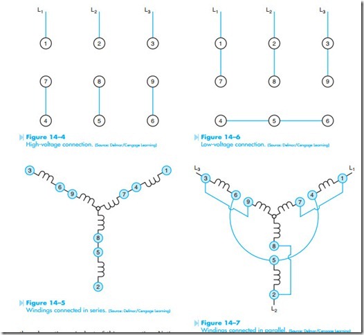
Figure 14–4 shows the stator connection for operation on a 480-volt line. Figure 14–5 shows the motor. Some motors, for example, are started as a wye-connected stator to help reduce starting current, and then changed to a delta connection for running.
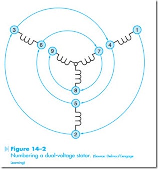
Many three-phase motors have dual-voltage stators. These stators are designed to be connected to 240 volts or 480 volts. The leads of a dual-voltage stator use a standard numbering system. Figure 14–2 shows a dual-voltage wye-connected stator. Notice
the stator leads have been numbered in a spiral. This diagram shows that numbers 1 and 4 are opposite ends of the same coil. Lead number 7 begins another coil, and this coil is to be connected to the same phase as 1 and 4. Leads 2 and 5 are opposite ends of the same coil. Coil number 8 must be connected with the same phase as leads 2 and 5. Leads 3 and 6 are opposite ends of a coil and must be connected with lead number 9. Keep in mind that Figure 14–2
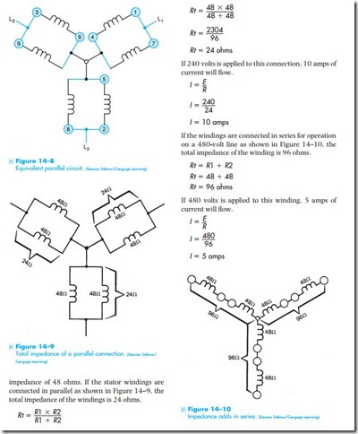
the schematic equivalent of this connection. Notice that the windings have been connected in series. Figure 14–6 shows the stator connection for operation on a 240-volt line. Figure 14–7 shows the schematic equivalent of this connection. When the motor is to be operated on 240 volts, the stator windings are connected in parallel. Notice that leads 4, 5, and 6 are connected together to form another center point. This centerpoint is electrically the same as the point where leads 7, 8, and 9 join together. Figure 14–8 shows the equivalent circuit.
When a motor is operated on a 240-volt line, the current draw of the motor is double the current draw of a 480-volt connection. For example, if a motor draws 10 amps of current when connected to 240 volts, it will draw 5 amps when connected to 480 volts. The reason for this is the difference of impedance in the windings between a 240-volt connection and a 480-volt connection. For instance, assume the stator windings of a motor have an


