HIGH-EFFICIENCY FURNACES
Newer furnaces (those made since 1981) have been designed with efficiencies of up to 97 percent, as com- pared to older types with efficiencies in the 60 percent range. The Lennox Pulse™ is one example of the types available.
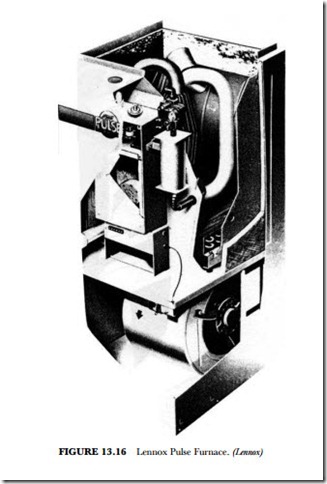
The G-14-series pulse-combustion up-flow gas furnace provides efficiency of up to 97 percent. Eight models for natural gas and LPG are available with input capacities of 40,000, 60,000, 80,000, and 100,000 Btuh. The units operate on the pulse-combustion principle and do not require a pilot burner, main burners, con- ventional flue, or chimney. Compact, standard-sized cabinet design, with side or bottom return-air entry, permits installation in a basement, utility room, or closet. Evaporator coils may be added, as well as electronic air cleaners and power humidifiers (see Figure 13.16).
Operation
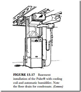
The high-efficiency furnaces achieve that level of fuel conversion by using a unique heat-exchanger design. It features a finned cast iron combustion chamber, temperature-resistant steel tailpipe, aluminized steel ex- haust-de-coupler section, and a finned stainless steel tube condenser coil similar to an air-conditioner coil. Moisture from the products of combustion is condensed in the coil, thus wringing almost every usable Btu out of the gas. Since most of the combustion heat is utilized in the heat transfer from the coil, flue vent temperatures are as low as 100 F to 130 degrees F, allowing for the use of 2-inch-diameter polyvinyl chloride (PVC) pipe. The furnace is vented through a side wall or roof or to the top of an existing chimney with up
to 25 feet of PVC pipe and four 90-degree elbows. Condensate created in the coil may be disposed of in an indoor drain (see Figure 13.17). The condensate is not harmful to standard household plumbing and can be drained into city sewers and septic tanks without damage.
The furnace has no pilot light or burners. An automotive-type spark plug is used for ignition on the initial cycle only, saving gas and electrical energy. Due to the pulse-combustion principle, the use of atmospheric gas burners is eliminated, with the combustion process confined to the heat-exchanger combustion chamber. The sealed combustion system virtually eliminates the loss of conditioned air due to combustion and stack dilution. Combustion air from the outside is piped to the furnace with the same type of PVC pipe used for exhaust gases.
Electrical Controls
The furnace is equipped with a standard-type redundant gas valve in series with a gas-expansion tank, gas- intake flapper valve, and air-intake flapper valve. Also factory installed are a purge blower, spark plug ig- niter and flame sensor with solid-state control circuit board. The standard equipment includes a fan and limit control, a 30-VA transformer, blower cooling relay, flexible gas-line connector, and four isolation mounting pads, as well as a base insulation pad, condensate drip leg, and cleanable air filter. Flue vent/air intake line, roof- or wall-termination installation kits, LPG conversion kits, and thermostats are available as accessories and must be ordered extra, or you can use the existing ones when replacing a unit.
The printed circuit board is replaceable as a unit when there is a malfunction of one of the components. It uses a multivibrator transistorized circuit to generate the high voltages needed for the spark plug. The spark plug gets very little use except to start the combustion process. It has a long life expectancy. The spark gap is 0.115 inch, and the ground electrode is adjusted to 45 degrees (see Figure 13.20).
Sequence of Operation
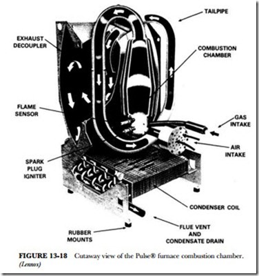
On a demand for heat, the room thermostat initiates the purge blower operation for a prepurge cycle of 34 seconds, followed by energizing of the ignition and opening of the gas valve. As ignition occurs, the flame sensor senses proof of ignition and de-energizes the spark igniter and purge blower (see Figure 13.18). The furnace blower operation is initiated 30 to 45 seconds after combustion ignition. When the thermostat is
satisfied, the gas valve closes, and the purge blower is re-energized for a postpurge cycle of 34 seconds. The furnace blower remains in operation until the preset temperature setting (90 degrees F) of the fan control is reached. Should the loss of flame occur before the thermostat is satisfied, flame sensor controls will initiate three to five attempts at reignition before locking out the unit operation. In addition, loss of either combus- tion intake air or flue exhaust will automatically shut down the system.
Combustion Process
The process of pulse combustion begins as gas and air are introduced into the sealed combustion chamber with the spark-plug igniter. Spark from the plug ignites the gas/air mixture, which in turn causes a positive pressure buildup that closes the gas and air inlets. This pressure relieves itself by forcing the products of com- bustion out of the combustion chamber through the tailpipe into the heat-exchanger exhaust decoupler and on into the heat-exchanger coil. As the combustion chamber empties, its pressure becomes negative, draw- ing in air and gas for ignition of the next pulse. At the same instant, part of the pressure pulse is reflected back from the tailpipe at the top of the combustion chamber. The flame remnants of the previous pulse of combustion ignite the new gas/air mixture in the chamber, continuing the cycle.
Once combustion is started, it feeds on itself, allowing the purge blower and spark igniter to be turned off. Each pulse of gas/air mixture is ignited at the rate of 60 to 70 times per second, producing one-fourth to one-half Btu per pulse of combustion. Almost complete combustion occurs with each pulse. The force of these series of ignitions creates great turbulence, which forces the products of combination through the en- tire heat-exchanger assembly, resulting in maximum heart transfer (see Figure 13.18).
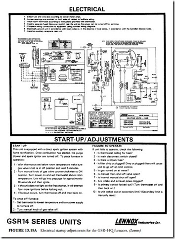
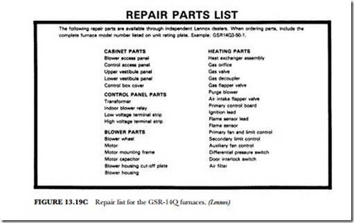
Startup procedures of the GSR-14Q series of Pulse furnaces, as well as maintenance and repair parts, are shown in Figure 13.19A-C.
Troubleshooting The Pulse™ Furnace
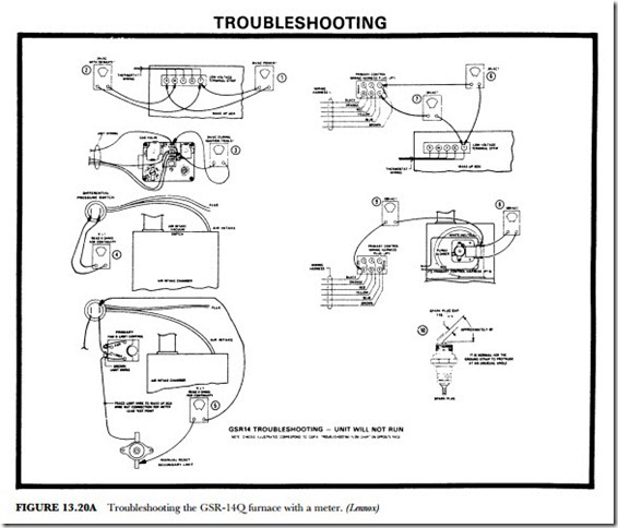
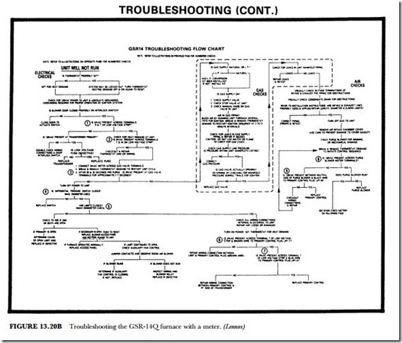
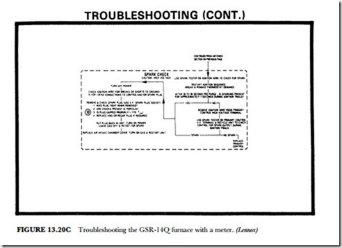
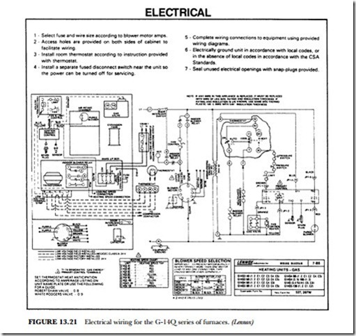
Troubleshooting procedures for the Pulse™ furnaces are shown in Figures 13.20 A-C. Figure 13.21 shows the circuitry for the G-14Q series of furnaces. Note the difference in electrical circuitry for the G-14 and GSR-
14. Blower-speed color-coded wires are also indicated for the different units. The 40, 60, 80, and 100 quali- fication after G-14Q indicates whether it is a 40,000, 60,000, 80,000, or 100,000 Btuh unit. Thermostat heat anticipation is also given for the Robertshaw valve and the Rodgers valve. This type of electrical diagram is usually glued to the cabinet so that it is with the unit whenever there is a need for troubleshooting.
The troubleshooting flow chart is typical of those furnished with newer equipment in the technical man- uals the dealers provide. After locating the exact symptoms, check with the other part of Figure 13.20 to find how to use the multimeter to check out all the circuitry to see if the exact cause of the problem can be de- termined.
