Locations and Clearances
The proper location of a gas furnace depends on a careful consideration of the following three factors:
1. Length of heat runs
2. Chimney location
3. Clearances
A gas forced-air furnace should be located as near as possible to the center of the heat-distribution system and chimney. Centralizing the furnace reduces the need for one or more long supply ducts, which tend to lose a certain amount of heat. The number of elbows should also be kept to a minimum for the same reason. Installing the furnace near the chimney will reduce the length of the horizontal run of flue pipe required for the traditional, standing- pilot type gas furnace. The flue pipe should always be kept as short as possible.
Sufficient clearance should be provided for access to the draft hood and flue pipe. It is particularly important to locate a gas-fired furnace so that the draft hood is at least 6 in from any combustible material.
Allowing access for lighting the furnace and servicing it is also an important consideration. Most furnace manufacturers recom- mend a clearance of 24 to 30 inches in front of the unit for access to the burner and controls.
Clearances between the furnace and any combustible materials are usually provided by the manufacturer in the furnace specifications.
Wiring
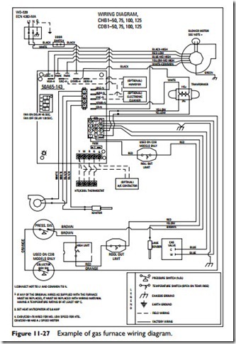
All of the electrical wiring inside the furnace is completed and inspected at the factory before the unit is shipped. Wiring instructions will accompany each furnace and the internal (factory installed) wiring will be clearly marked. The wiring to controls and to the electrical power supply must be completed by the installer, and the wiring should be done in accordance with the diagram sup- plied by the manufacturer. This wiring is usually indicated on wiring diagrams by broken lines.
All wiring connected to the furnace must comply with the latest edition of the National Electric Code and any local codes and ordinances. Local codes and ordinances will always take precedence over national ones when there is any conflict. In order to validate the furnace warranty, many manufacturers require that a local electrical authority approve all electrical service and connections.
The two types of electrical connections required to field wire a furnace are (1) line-voltage field wiring, and (2) control-voltage field wiring. Both are illustrated in the wiring diagram for the gas furnace shown in Figure 11-27.
The line-voltage wiring connects the furnace to the building power supply. It runs directly from the building power panel to a fused disconnect switch. From there, the wiring runs to terminals L1 and L2 on the power-supply terminal block (that is, the furnace junction box).
The unit must be properly grounded either by attaching a ground conduit for the supply conductors or by connecting a separate wire from the furnace ground lug to a suitable ground. The furnace must be electrically grounded in accordance with the National Electrical Code (ANSI-CI-1971).
Furnaces equipped with motors in excess of 3⁄4-hp or 12-amp ratings must be wired to a separate 240-volt service in accordance with the National Electrical Code and local codes and regulations. A 240-volt transformer should be installed whenever 240-volt service is required and/or a motor larger than 3⁄4 hp is used.
The external control-voltage circuitry consists of the wiring between the thermostat and the low-voltage terminal block located in the control-voltage section of the furnace. Instructions for the control-voltage wiring are generally shipped with the thermostat.
Duct Connections
The warm-air plenum, warm-air duct, and return-air duct should be installed in accordance with the furnace manufacturer’s specifications and the local building code requirements. Detailed information about the installation of an air-duct system for a gas furnace is also contained in the following publications:
1. Residence Type Warm Air Heating and Air Conditioning System (National Fire Protection Association, No. 90B)
2. Installation of Air Conditioning and Ventilating Systems of Other than Residence Type (National Fire Protection Association, No. 90A)
3. Manual D, Residential Duct Systems (Air Conditioning Contractors of America)
Additional information about duct connections can be found in Chapter 7 of Volume 2, “Ducts and Duct Systems.”
It is important for you to remember the following facts about furnace duct connections and the air distribution ducts:
1. Duct lengths should be kept to a minimum by centralizing the furnace location as much as possible.
2. The duct system must be properly sized. Undersizing will cause a higher external static pressure than the one for which the furnace was designed. This may result in a noisy blower or insufficient air distribution.
3. Duct sizing should include an allowance for the future installation of air conditioning equipment.
4. The furnace should be leveled before any duct connections are made.
5. Seal around the base of the furnace with a caulking com- pound to prevent air leakage if a bottom air return is used.
6. Ducts should be connected to the furnace plenums with tight fittings.
7. Warm-air-plenum and return-air-plenum connections should be the same size as the openings on the furnace.
8. Use tapered fittings or starter collars between the ducts and the furnace plenum.
9. Ductwork located in unconditioned spaces (for example, unheated attics, basements, and crawl spaces) should be insulated if air conditioning is planned for some future date.
10. Install canvas connectors between air plenums and the casing of the furnace to ensure quiet operation. Check local codes and regulations to make certain canvas connectors are in compliance.
11. Line the first 10 ft or so of the supply and return ducts with acoustical material when extremely quiet operation is necessary.
12. Install locking-type dampers in each warm-air run to facilitate balancing the system.
