Stirling Cycle
The Ideal Stirling Cycle
We have pointed out again and again that effective energy conversion requires the reduction of internal and external irreversibilities as much as possible. An important cause of external irreversibility is heat transfer between the system and its heat sources and sinks, e.g., a stream of combustion gas, or the environment. The related loss can be reduced if heat that is rejected in one process of a cycle can be added elsewhere within the system. This simultaneously reduces the heat rejection and the heat supply from the exterior, thus leading to efficiency improvements. Indeed, regeneration, i.e., internal exchange of heat within a system, is the most important tool to reduce external irreversibilities, and increase efficiency. Historically, the first engine which used a regenerator was the Stirling engine.
The idealized Stirling cycle consists of two isothermal and two isochoric processes, taking place at temperatures TH and TL, and volumes V1, V2, respectively. The working medium is an ideal gas, e.g., air or helium, which is confined permanently in a cylinder. The T-S- and p-V-diagrams are depicted in Fig. 13.1.
We ignore all internal irreversibilities, so that work and heat for the reversible processes within the ideal Stirling cycle are
Since internal energy of the ideal gas depends only on temperature, u = u (T ), it turns out that the heats exchanged during the isochoric processes are equal, but of opposite sign,1
With this, the heat q23, which is rejected during the isochoric cooling process, can be used for the isochoric heating q41. In the Stirling engine, this is done by means of the regenerator, which allows for internal heat exchange. The working principle of the regenerator will be discussed further below.
When a regenerator is employed, the heat q41 is exchanged internally, and only the heat q12 must be provided from the outside, e.g., by burning a fuel.
The thermal efficiency is obtained, with (13.1), as
In case that TL and TH are the temperatures of reservoirs with which the cycle exchanges heat, the above is just the Carnot efficiency, that is the maximum efficiency for a process operating between reservoirs at temperatures TH and TL. It follows that the ideal Stirling process with regenerator is a realization of a Carnot engine, as long as the heat transfer with the reservoirs takes places at infinitesimal temperature difference.
We note that the amounts of heat exchanged during the isochoric processes, q23 and q41, can only be equal in size for an ideal gas (with variable or constant specific heats), for which internal energy does not depend on specific volume, u = u (T ) and not u = u (T, v). This is different for the Carnot cycle—another realization of a Carnot engine—which has the same efficiency independent of the working medium.
Although the efficiency is independent of the type of ideal gas used, most Stirling engines use helium or hydrogen as working medium. The high heat conductivity of gases with low molecular masses leads to a faster heat ex- change and thus allows to operate the engine at a higher frequency.
The power output of the engine depends on the mass m enclosed in the cylinder, and the rotation speed n˙ of the engine,
Fast changes in power demand, as they are necessary for use in cars, can be achieved by changing the amount of working gas in the cylinder, i.e., by pumping additional mass in or out. This, of course, adds to the complexity of the process. It is therefore no surprise that most of today’s applications of the Stirling engine consider systems which run at constant load, and generate electricity, in particular with heat supply from solar collectors.
Working Principle of a Stirling Engine
It is difficult, if not impossible, to build an engine that operates on the ideal Stirling cycle. All real Stirling engines approximate the ideal cycle to some extent. There are many different working principles for Stirling engines, and here we discuss the operating principle of a Leybold Stirling engine for use in teaching laboratories, which operates in the same way as the original Stirling engine.2
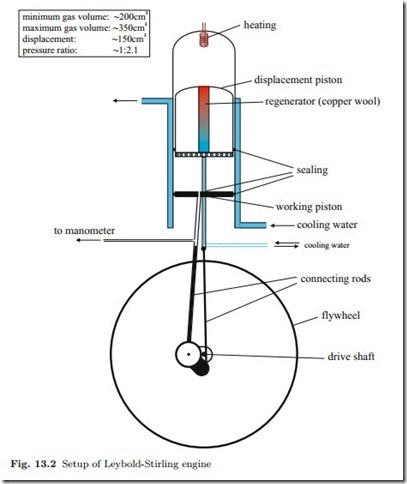
The lab engine, sketched in Fig. 13.2, consists of a glass cylinder in which two pistons—the working piston and the displacement piston—move vertically with a phase shift of 90◦. Mounted on top of the cylinder is the heating coil (electrical heating), which maintains the upper part of the engine at high temperature (TH ). The lower part of the cylinder is encased by a second glass cylinder, with cooling water flowing between the two cylinders and through the bottom of the displacement piston to maintain the lower part of the engine at low temperature (TL).
The displacement piston shifts the gas between the upper high- temperature part of the engine and the lower low-temperature part. The movement of the displacement piston forces the gas through a cylindrical hole in the displacement piston that is filled with copper wool which acts as the regenerator. As the gas passes from the hot part of the engine to the cold part, the gas cools gradually by giving up heat to the copper wool. On the way back the gas takes heat from the regenerator and is thus gradually heated. The working piston seals the gas against the environment and serves to compress or expand it while exchanging work with the environment.
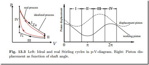
The actual thermodynamic cycle of the Stirling engine differs somewhat from the idealized Stirling cycle, see Fig. 13.3 for a qualitative comparison
of the idealized and the real cycle. In order to understand how the Stirling engine approximates the ideal cycle, it is best to study the p-V-diagram in Fig. 13.3, which also shows the displacement of the two pistons as function of the shaft angle.
I. Isothermal expansion: The displacement piston is at bottom dead center, almost at rest, so that most of the working gas is in the upper hot zone. The working piston moves downward and the gas expands, the heat supplied is transferred to work.
II. Isochoric cooling: The working piston is at bottom dead center, so that the total gas volume is (almost) fixed. The displacement piston is moving upwards and the working gas streams into the lower cold part of the engine. While flowing through the regenerator (copper wool), the gas transfers heat to the regenerator.
III. Isothermal compression: The displacement piston is at top dead center, and the working gas is in the lower cool part of the cylinder. The working piston moves upwards compressing the gas. The gas releases heat to the cooling water so that the gas temperature remains nearly constant.
IV. Isochoric heating: The working piston is at top dead center, while the displacement piston is moving downwards. The cool gas is streaming upwards through the regenerator, where it receives the energy which was stored in Step II.
The main reasons why the measured p-V-diagram deviates from the ideal one, and assumes the more oval form shown in Fig. 13.3 are:
1. Truly isochoric processes require that the working piston is at rest. How- ever, since it is driven by a crankshaft, the working piston moves sinusoidally.
2. Compression and expansion (I and III) are fast, and do not take place isothermally.
3. The heating coil releases heat into the gas at all times, not only during step I .
4. Part of the working gas remains in the cool part of the engine at all times.
5. The regenerator is not 100% efficient.
6. Heat losses to the environment and friction dissipate energy.
7. Insufficient sealing leads to exchange of gas with the outside.
The Reverse Stirling Cycle
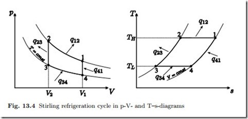
A Stirling engine can also operate as a refrigeration engine or a heat pump. In both cases the engine is driven by a motor, and the process curve in the p-V-diagram runs counter-clockwise, see Fig. 13.4 for the ideal process curve. During the isothermal processes (1-2, 3-4) heat is exchanged with the environment of the engine, while the heat transfer during the isochoric processes (2-3, 4-1) is an internal heat exchange by means of the regenerator.
We find for the branches of this cycle the following exchange of heat and work with the environment:
for a heat pump, respectively. Again, these are the COP’s of the respective Carnot engines, i.e., the maximum COP’s that can be reached between the temperatures TH , TL.
The lab engine can run as both, heat pump and refrigerator. If run as a heat pump, the lower, water cooled, part of the engine is the cold part of the engine (at TL) and heat is pumped to the upper part of the engine which becomes hot (TH ). When the operating direction of the engine is reversed, the lower, water cooled, part of the engine becomes the hot part of the engine (at TH ) and heat is pumped away from the upper part of the engine which becomes cold (TL), the engine operates as a refrigerator.
Stirling Engines Then and Now
The Stirling engine was patented in 1816 by Robert Stirling (1790-1878), a minister of the Church of Scotland. At that time, steam engines had a rather low efficiency (2-10%), and were quite unsafe. Boilers exploded often, and the high pressure steam that was released had scalding effects. The Stirling hot-air engine was promising to overcome both problems: The regenerator gave it a good efficiency, and in the unlikely case of a bursting engine, only hot air was released so that the consequences of an accident were far less severe. However, the Stirling engine could never live up to the expectations. While the steam turbine was improved more and more to today’s efficiencies of over 45%, and internal combustion engines, i.e., Otto and Diesel engines, prevailed for the use in cars and trucks, Stirling engines almost vanished from the scene.
Unlike an internal combustion engine, a Stirling engine does not exchange the working gas in each cycle, but contains the gas permanently. The heat is supplied outside the engine, so that any heat source is suitable to power a Stirling engine. Thus, a Stirling engine can be driven by carbon fuels (coal, natural gas, gasoline, Diesel oil), hydrogen, solar radiation, nuclear power, waste heat of industrial processes, etc. If a fuel is used, it is burned continuously, with lower emissions than in a reciprocating internal combustion engine.
Stirling refrigeration engines can give very low temperatures, and are widely used for small scale cryogenic cooling. A promising application for Stirling heat engines is the conversion of solar energy into electricity by mean sof parabolic mirror dishes with Stirling engines in the focus. While these devices can only operate under direct sunlight, they can be far more efficient than photovoltaic cells.
At present it is not possible to build a high efficiency Stirling engine at a competitive price. In order to have a high specific power (kW per litre of engine capacity), the working gas must be highly pressurized (goal: up to 190 bar), causing problems of sealing against the environment and lubrication. It is at the seals where a large portion of mechanical losses occur. The efficiency increases with the temperature difference between the cold and the hot part of the engine. Thus, highly efficient engines require non-standard materials that can operate at temperatures of 750 ◦C and more.


