Gas Piping for Conversion Burners
Gas piping is generally wrought iron or steel with malleable iron pipe fittings. Joint compound (pipe dope) is applied sparingly to the male threads only. Make certain before applying the joint compound that it is approved for all types of gas. Never use aluminum tubing or cast- iron fittings on the main gas line. Soldered or sweated connections are also not recommended.
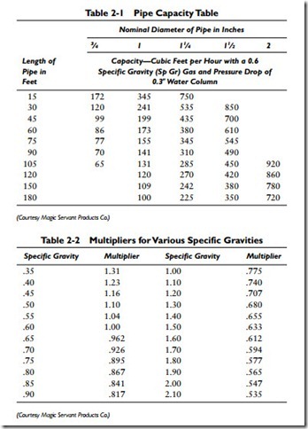
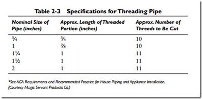
Tables 2-1 and 2-2 can be used to determine the size of pipe to use from the meter to the gas burner. The correct number of threads for any particular length of pipe is given in Table 2-3.
*See AGA Requirements and Recommended Practice for House Piping and Appliance Installation. (Courtesy Magic Servant Products Co.)
Use pipe fittings at all turns in the gas line. Never bend or lap welded pipe because it will pinch or weaken it. Support the pipe with straps, bands, pipe hooks, or hangers (never allow one pipe to rest on another or to sag).
Pitch all horizontal pipe so that it grades toward the meter with- out the occurrence of sags. The piping should be protected against freezing and the accumulation of condensation.
Pipes and pipe fittings that are defective should be replaced, never repaired. Every effort must be made to eliminate any possibility of gas leakage. Gas leaks on pipes and pipe fittings should be located by spreading a soap solution over the surface. Never try to locate a gas leak with a flame. The results could be extremely hazardous.
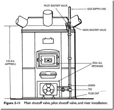
Figure 2-11 illustrates the general configuration of the main shutoff valve, pilot shutoff valve, and riser installation for a gas conversion burner. The following suggestions are worth noting:
1. Install the main manual gas shutoff valve on the riser at least 4 ft above the floor level.
2. Install the pilot valve on the inlet side of the main manual gas shutoff valve.
3. Install a tee fitting at the bottom of the riser to catch any foreign matter in the pipe. The bottom of the tee fitting should be plugged or capped.
4. Install a ground joint union in the gas line between the burner air duct box and the tee fitting in the riser.
5. Install a pilot supply line (1⁄4-in OD tubing) between the pilot valve and a point located on the upper right side of the air duct box on the gas burner. This line will run parallel to the riser.


