Pressure Regulators
Natural gas is distributed through the city mains at pressures of 7 inches water gauge or higher. Normally this gas will be at a higher pressure than the heating equipment or appliance can properly use. Furthermore, the gas pressure in the mains (and in the building sup- ply lines) will often fluctuate because of load demand variations. Excessively high gas pressure and gas-pressure variations are detrimental to the operating efficiency and safety of a gas-fired furnace, boiler, or water heater. Hence, they must be brought under control before the gas enters the burners.
A gas-pressure regulator (or manifold pressure regulator as it is also called) is a regulating device used to control manifold gas pressure. Gas is delivered to the burners from the outlet orifice of the regulator at a single, nonfluctuating constant pressure regardless of inlet pressure changes.
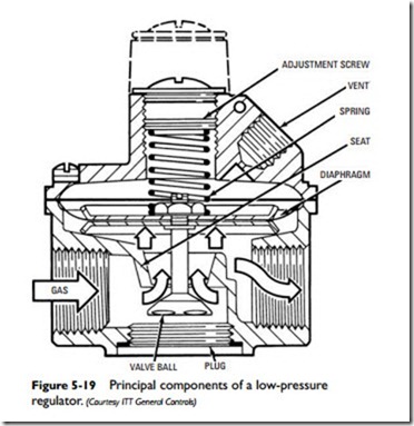
A regulator must sense all changes in gas pressure and be able to adjust the gas flow as required. The sensing device by which this is accomplished is a diaphragm and spring arrangement attached to a valve ball or disc used to restrict gas flow through the seat. These and other components are illustrated in the cutaway of the low- pressure regulator shown in Figure 5-19.
A pressure regulator uses the available gas pressure as the pri- mary force to open or close the valve. Outlet gas pressure presses against the diaphragm and spring. If the gas pressure is too little to overcome the force of the spring, then the attached ball or disc is pushed away from its seat. This enlarged opening allows more gas to flow. If the outlet pressure against the diaphragm is greater than the spring setting, then the valve ball or disc is brought toward its seat, narrowing the opening and restricting flow. As the gas pres- sure against the diaphragm equals the force exerted by the spring, the valve ball or disc is so positioned from the orifice to maintain a steady downstream pressure. This principle of operation is basic to all diaphragm valves.
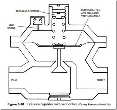
The spring-loaded side of the diaphragm must be vented or the movement of the diaphragm will be restricted. The most elementary form of venting is shown in Figure 5-20. This is simply an orifice installed in a vent hole on the spring-loaded side of the
diaphragm. A more complex method of venting involves connecting a tube to a tapping in the vent. This represents either the internal or external bleed system of venting gas. The principal difference between the two systems lies in how and where the vented gas is disposed.
Proper venting allows the valve diaphragm to move freely in either direction. Installing an orifice in the vent hole slows the diaphragm action, thereby providing a smoother operating control (see Figure 5-20). The use of a vent hole orifice also prevents the rapid and potentially dangerous escape of gas in the event of a diaphragm rupture.
Both internal and external bleed systems are used to vent the gas from the spring-loaded side of the diaphragm. In an internal bleed system, the bleed gas is routed to the burner or pilot where it is burned, or to the burner manifold where it is mixed with the main
gas supply and eventually burned. In an external bleed system, the bleed gas is vented by a tube extending to the outdoors. A variation of the external bleed system is to place the outlet end of a tube in the heat exchanger to vent the gas outside.
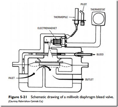
A simple diaphragm valve functions only to open or close the valve and is generally of the external bleed type (see Figure 5-21). The operator mechanism for a restricting internal bleed orifice diaphragm valve is basically as shown in Figure 5-22.
A gas-pressure regulator can be either an independent control on a gas manifold or a part of a combination gas control. The obvious advantage to using a combination control is the simplification of appliance assembly and the saving of space obtained when com- pared to the use of separate components. Less obvious are the operational advantages.
When the pressure regulator is not an integral part of the combination gas control, it either precedes or follows the location of the
latter in the manifold. If the separate pressure regulator precedes the combination control, both the main burner gas and the pilot gas are regulated by the same regulator in most installations. If this is the case, a problem will sometimes occur with pilot outage. As the main gas valve opens to provide gas to the main burners, a temporary starving of the pilot gas can occur due to regulator response delay. This condition can be avoided by installing a separate pilot gas regulator for pilot gas only or by using a regulator-equipped combination gas control with the proper sequencing of operation.
Installing a separate pressure regulator after the combination gas control (i.e., downstream from it) can sometimes result in over- gassing the main burners. This occurs because the regulator remains in a wide-open position when the main gas valve remains closed. When the gas valve opens, overgassing can result from the delay of the regulator valve in resuming regulation. A combination gas control can eliminate this problem.
Some gas-fired water heaters use a balanced pressure regulator. This type of pressure regulator uses two internal diaphragms to control gas pressure. The operating principle is quite different from that described for the regulators used on gas-fired heating equipment. For additional information, read the section Balanced Pressure Regulators in Chapter 4 of Volume 3 (W“
Related posts:
Incoming search terms:
- spring-loaded constant pressure appliance regulator
- 58 Gas Pressure Regulators Gas Turbines Steam Turbines Marine power Pressure Vessels industrial power Drilling machineries fluid control devices Drilling Equipment chemical pumps Industrial Valve Pump Oil and gas Auxiliary equipment in Venezuela mail
- Pressure Control Equipment mail


