Cadmium Cell Primary Controls
A cadmium cell primary control consists of a primary control assembly operating in conjunction with a cadmium detection cell.
The cadmium detection cell is considered the most effective sensor used to monitor the burner flame. It consists of a light-sensitive photocell, a holder, and a cord assembly (see Figure 5-80). The sur- face of the detection cell is coated with cadmium sulfide and over- laid with a conductive grid. Electrodes attached to the detection cell are used to transmit an electrical signal to the primary control.
The variable resistance of this surface to the presence of light (i.e., the burner flame) is used to actuate the flame detection circuit. When light is present (in the form of the burner flame), the resistance of the cadmium sulfide surface to the passage of electrical current is very low. Consequently, as long as the burner flame lasts, an electrical current will pass between the cadmium detection cell and the primary control unit, and the burner motor on cycle will continue operating. If the burner flame should fail or if ignition should fail to occur, the resistance of the cadmium sulfide surface to the passage of electrical current will be very high. This will interrupt the passage of the electrical current to the primary control and will cause the latter to shut off the burner motor.
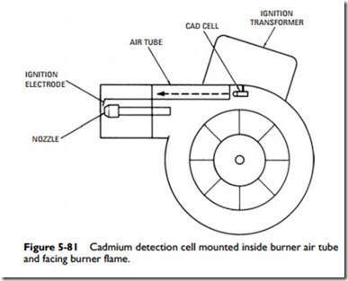
The detection cell is mounted inside the burner air tube so that it faces the burner flame (see Figure 5-81). The exact location of
the detection cell is determined by the oil burner manufacturer and dictated by the design of the oil burner. In any event, the detection cell must be placed so that it views the burner flame directly. The fact that the detection cell responds to any light source means that it must be located where its surface will be shielded from any form of direct or reflected external light. Moreover, the ambient temperature should be kept below 140F because excessive temperatures can also cause the detection cell to malfunction.
Sometimes a malfunctioning oil burner will cause a heavy layer of soot to accumulate on the cell surface. The cell surface should be carefully wiped to remove the soot and restore full view of the oil flame. A damaged detection cell should be replaced.
The type of primary control used with a cadmium detection cell will depend on the type of controller voltage, the type of ignition system, and the length of safety switch timing required by the installation.
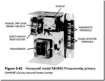
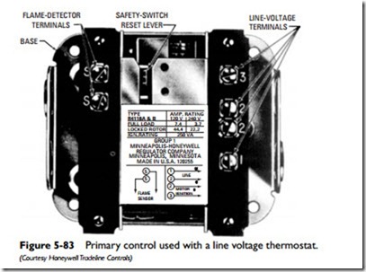
The Honeywell R8184G Protectorelay primary control shown in Figure 5-82 has a transformer included in the unit to supply 24-volt power to the control circuit. This is a low-voltage primary, and it requires a 24-volt thermostat. Other models are available that require a line voltage controller (see Figure 5-83).
The primaries illustrated in Figures 5-82 and 5-83 are designed for use with nonrecycling constant-ignition oil burners. Automatic recycling control of an intermittent-ignition oil burner can be obtained by using the primary shown in Figure 5-84. The basic dif- ferences between the constant-ignition and intermittent-ignition sys- tems can best be illustrated by the wiring diagrams shown in Figures 5-85 and 5-86. An intermittent-ignition system contains the same components as a constant-ignition system plus the following:
1. A interlock contact in the ignition circuit (T1).
2. An ignition timer heater (T).
3. An interlock contact (T2) in the circuit between the safety switch heater (SS) and the ignition timer heater (T).
Safety switch timing can be 15, 30, 45, or 80 seconds depending on the manufacturer and model.


