Potential (voltage) relay
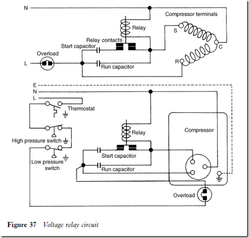
This type of relay is used with high starting torque motors. It operates in a similar manner to the current relay except that the switch contacts are normally closed. The solenoid coil, once energized, maintains a magnetic force strong enough to open the switch contacts and keep them open whilst the compressor is running.
The relay has a much higher design voltage rating than the supply voltage. As the motor approaches its design speed, the voltage across the coil can sometimes be more than twice that of the supply voltage.
When power is supplied to the circuit, the relay contacts are closed. Both motor windings are energized and starting is achieved. As the motor increases speed, the voltage in the start winding increases to cause an increase in both voltage and current passing through the coil. When the design voltage of the coil is reached, the current creates a strong magnetic force to pull in the plunger and contact bridge to open the start circuit, but allows the compressor to operate on the run winding.
When the relay contacts open, the voltage and current across the coil will decrease but will maintain a magnetic force strong enough to keep the contacts open until power is disconnected. The contacts will then return to the closed position ready for a restart.
This relay is wired in parallel, unlike the current type which is wired in series. A voltage relay circuit is shown in Figure 37.
Solid state starting devices
Semiconductor starting devices are used on domestic and commercial units with fractional horsepower motors. Some versions are not recommended for permanent installation but are used rather as emergency replacements, because they may not always be suitable for the motor design characteristics.
Positive temperature coefficient (PTC) device
Many commercial motor compressors have this type of starting device. In most cases the motor is designed with an internal overload protector; this gives better protection against overload conditions since it is more sensitive to the temperature of the motor windings. It is less current sensitive than the external overload protector.
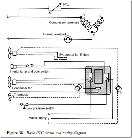
When the compressor starts, resistance in the semiconductor is low and current can pass freely to the start winding. As the current flows it heats the semiconductor (in approximately 2 to 3 seconds). This causes an increase in resistance through the semiconductor, thereby reducing the flow of current; by this time the motor is up to speed. The reduced current flow is sufficient to maintain the heat in the semiconductor and prevent high current flow to the start winding, allowing the compressor to operate on the run winding.
In the event of a starting failure the increased current drawn will also cause a rise in temperature of the motor windings and actuate the overload protector. Obviously current will not flow to the start winding after a starting failure. The semiconductor has to cool before another starting attempt can be made, and there is therefore greater motor protection.
A further advantage of this type of starting device is that it does not have any moving parts, unlike current and voltage relays. This lessens the risk of failure due to wear and corrosion of contacts. It also makes it more acceptable where stringent demands are made for low noise levels; arcing across switch
contacts can affect tape recorders, videos and other domestic and industrial electronic equipment.
The normal cooling period before a restart is 3 to 5 minutes. The protector cut-out temperature is about 140°C or 285°F, and the cut-in temperature is about 105°C or 220°F. At 140°C the cooling period before the compressor can restart may be as long as 45 minutes, depending upon the ambient temperature.
A basic PTC circuit and wiring diagram is shown in Figure 38.
IC-22 relay
This is another form of solid state relay for non-capacitor and capacitor start motors. It can be used as a replacement for the conventional types.
The normal operating temperature of the semiconductor is approximately 76°C or 170°F. Therefore care must be taken when handling if the compressor is running.
Installation for non-capacitor start motors is as follows:
1 Remove the defective relay but leave the overload protector in place if it is serviceable.
2 Connect one lead of the IC relay to the compressor start terminal.
3 Connect temperature/pressure controls, fans etc. to the run lead of the compressor using the quick connector provided.
For capacitor start motors, follow steps 1, 2 and 3, then adapt the compressor wiring to connect the capacitor in series.
Note that if the overload protector is an integral part of the defective relay which has been removed, there will be no overload protection for the motor. A suitable overload must be selected and fitted.
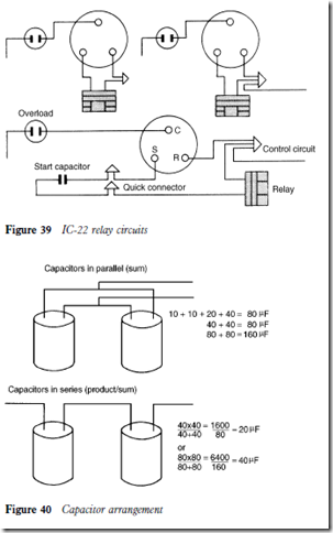
Figure 39 shows the electrical connections for an IC-22 relay.
Capacitors
Those normally used on smaller units are of the electrolytic type. They can be considered as being an electrochemical component employed to improve the phase angle relationship between the motor windings when the motor starts and runs.
They may be installed in a series or parallel with the motor windings. If a specific capacitance is not available as a direct replacement, two or more capacitors may be used. The capacitance is stamped on to the casing of a capacitor, and its value is given in microfarads.
A method of selecting and connecting capacitors for making up specific capacitances is given in Figure 40.


