AUTOMATIC CONTROLS
The automatic controls used in an electric heating system are designed to insure its safe and efficient operation. Detailed de scriptions of these controls are found in Chapter 4, Volume 2 (THERMOSTATS AND HUMID1STATS). This section is pri marily concerned with outlining the operating principles of the automatic controls used with an electric furnace. These controls include:
1. Room thermostat,
2. Thermostat heat anticipator,
3. Timing sequencers.
In a central heating system, the wall mounted room thermo stat is the control that governs the normal operation of the fur nace. The operating principle is simple. The temperature selector on the thermostat is set for the desired temperature. When the temperature in the room falls below this setting, the thermostat will call for heat and cause the first heating circuit in the furnace to be turned on. There is generally a delay of about 15 seconds before the furnace blower starts. This prevents the blower from circulating cool air in the winter. After about 30 seconds, the second heating circuit is turned on. The other circuits are turned on one by one in timed sequence.
When the temperature reaches the required level, the thermo stat opens. After a short period of time, the first heating circuit is shut off. The others are shut off one by one in timed sequence. The blower will continue to operate until the air temperature in the furnace drops below a specified temperature.
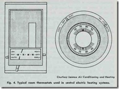
A typical room thermostat will have a fan switch, a system switch, and a temperature selector (Fig. 4). The temperature selector (a dial or lever device) on the thermostat is used to select the desired temperature. The actual operation of the heat ing system is governed by the positions of the fan and system switches. The switch positions and their functions are listed in Tables 1 and 2.
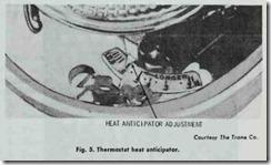
Most room thermostats contain a heat anticipator. This is a device designed to assist the thermostat in controlling closer to the desired temperature range (Fig. 5).
When timing sequencers are used (see below), the current flowing through the first time delay sequencer (relay) must also flow through the heat anticipator. In order to obtain satisfactory operation, the heat anticipator setting must be equal to the cur rent draw of the sequencer.
The furnace manufacturer will generally recommend the set ting for the heat anticipator adjustment for each size unit. For example, the setting recommended for a Trane Model EUADH 07 electric furnace is 0.45. This thermostat adjustment will vary de pending upon the type of time delay sequencer used, the furnace manufacturer, and the size of the furnace. This may be illus trated by the recommended heat anticipator settings given by Coleman for its 10 kW, 15 kW, and 20 kW furnace models (Table 3). All Coleman 25 kW models require a heat anticipator setting of 0.60.
After you have adjusted the heat anticipator to the suggested setting, operate the furnace several hours and observe the results. If there is insufficient heat, it may be caused by short furnace cycles. This can be corrected by moving the heat anticipator pointer to a slightly higher setting. If there is too much heat, then long furnace cycles are overheating the structure. This can be cor rected by moving the heat anticipator pointer to a slightly lower setting. After making these thermostat adjustments, allow the furnace to operate several hours to determine if further adjust ment will be required. Additional information about the thermostat heat anticipator is contained in Chapter 11 (GAS-FIRED FURNACES).
HEATING ELEMENTS
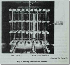
The heating elements in an electric furnace are resistance coils made from high temperature, chrome nickel heat generating wire. Most manufacturers design their furnaces so that the entire heat ing element assembly can be removed for easy maintenance or repair (Fig. 6).
TIMING SEQUENCERS
When all the heating elements in an electric furnace turn on simultaneously, there is a momentarily excessive demand on the power supply. The result is a temporary interruption in the elec trical service. This problem of power drains and surges can be eliminated by timing the heating elements so that they start one at a time in predetermined increments. Sequencing relays are used for this purpose.
SAFETY CONTROLS
Most electric-fired furnaces are equipped with a variety of different safety controls to protect the appliance against current overloading or excessive operating temperatures. These safety controls are:
1. Temperature limit controls.
2. Secondary high limit control.
3. Furnace fuses.
4. Circuit breakers.
5. Control voltage transformer.
6. Thermal overload protector.
TEMPERATURE LIMIT CONTROLS
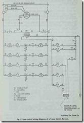
In the line control diagram of a Trane EVADH 07A model electric furnace shown in Fig. 7, each heating element is shown
with a high limit control device located between the heating ele ment and the time delay relay. These high limit control devices are designed to limit the outlet air temperature on Trane electric furnaces to 200°F. If the temperature of the outlet air should exceed 200°F., the high limit control will open and interrupt the supply of electric power to the heating element.
SECONDARY HIGH LIMIT CONTROL
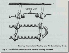
Secondary high limit protection is provided by a fusible link in each electric heating element (Fig. 8). This. device is designed to shut off the current when temperatures in the furnace become excessive. It functions as a back up system in case of limit switch failure.
FURNACE FUSES
Furnace fuses are used to provide protection against possible overload conditions, and to insure correct, safe field wiring.
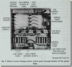
Each heating element circuit is protected by two branch fuses as shown in Fig. 9. These are sized to limit the current draw of each heater and are designed to open on a short circuit or an over loaded circuit condition. For overload protection, the blower motor and relay are also safeguarded with a separate fuse.
