Duct Furnaces
A duct furnace is essentially a unit heater designed for installation in a duct system. It is usually designed to operate on oil, natural gas, or propane gas, although electric duct heaters are also avail- able and growing in popularity.
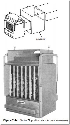
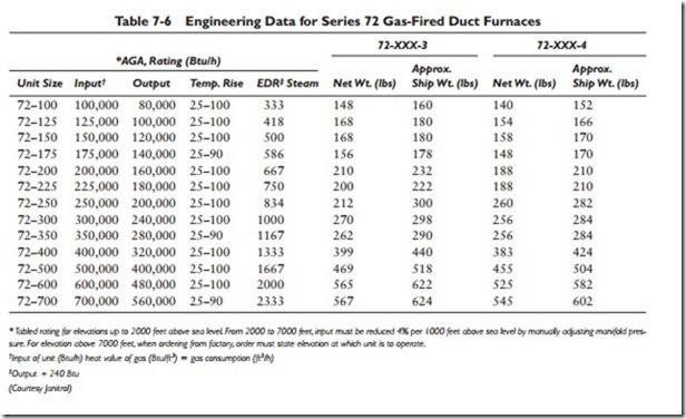
An example of a gas-fired (natural gas) furnace is the Janitrol 72 Series duct furnace illustrated in Figure 7-34, which is available in
13 sizes depending on the requirements of the installation. These are factory-assembled units inspected and tested before they are shipped. Once they reach their destination, they should be unpacked and the contents carefully checked against the packing list. Missing or damaged parts should be reported to the supplier immediately. This is a procedure you should follow habitually whenever you receive a shipment of equipment.
The design of these Janitrol duct furnaces is AGA-certified for use in a duct system with static pressure up to 2 inches of water and with temperature rises as shown in column 4 of Table 7-6.
Duct furnaces used in conjunction with cooling equipment should be installed in parallel with or on the upstream side of the cooling coils. If a parallel flow arrangement is used, the dampers (or other means of controlling the airflow) should be made tight enough to prevent the circulation of cooled air through the unit (see ANSI Z21.30).
When equipped with a suitable condensation pan, a duct furnace may be AGA-certified for installation downstream from cooling coils, air washers, and evaporative coolers when operating as air- cooling systems. In the Janitrol 72 Series duct furnace illustrated in Figure 7-34, the condensation pan is added in the following manner:
1. Remove the bottom panel of the duct furnace.
2. Remove the circular knockout section in the panel.
3. Place the condensation drain connection of the condensation pan in the opening.
4. Reinstall the bottom panel.
5. Connect the drain line.
6. Provide disconnect adjacent to bottom panel.
If space limitations prevent bottom-panel removal, access is possible through the front panel and burners (both of which must be removed before inserting the condensation panel).
Duct furnaces may be installed downstream of evaporative coolers or air washers considered as air-cooling systems (that is, operating with chilled water, which delivers air below the ambient air temperature at the duct furnace).
The minimum clearances between the duct furnace (and its draft hood) and the nearest adjacent walls, ceilings, and floors of com- bustible construction should be at least 6 inches (see ANSI Z21.30 and NEPA No. 31, Installation of Oil Burning Equipment 1972). Under certain circumstances the minimum clearance between the bottom of the duct furnace and the floor can be as close as 2 inches, provided the other clearances (that is, the 6-inch minimums) are maintained for the rest of the unit.
When planning duct furnace clearances, consideration must be given to accessibility for the following:
• Cleaning the heat exchanger
• Removal of burners
• Servicing the controls
The minimum clearance should be 18 inches for front removal of the burners and 10 inches for bottom removal.
The inlet and outlet ducts should be attached to the duct connec- tion flange. An access panel (or removable duct section) should be provided at both the inlet and outlet ducts to provide for servicing the limit and fan control elements. Moreover, such access should be so constructed as to provide for visual inspection of the heat exchangers.
In gas-fired duct furnaces, all gas piping must be run in accor- dance with requirements outlined in the American Gas Association’s publication Installation of Gas Appliances and Gas Piping.
It is recommended that a pipe joint compound certified for use with LPG be used on all pipelines. If possible, run a new gas supply line directly to the duct furnace from the meter. Support the gas line with hangers positioned close enough together to prevent strain on the unit. A trap consisting of a tee with a capped nipple should be provided in the gas line when the unit is installed. After installing the gas line, test it for leaks with a soap solution (never with a flame).
Oil- and gas-fired units must be properly vented. The draft head is built into these units, and the flue pipe must be the same size as the outlet of the flue collector on the duct furnace. Never reduce the size of the flue pipe or install a damper in it. Install the flue pipe to provide minimum clearances of 18 inches between it and com- bustible material. Always examine the chimney for proper con- struction and repair before connecting the flue pipe. Other details concerning venting practices are found in ANSI Z21.30 and NEPA No. 31, Installation of Oil Burning Equipment 1972. It is not nec- essary to vent electric-fired duct furnaces.
All electrical wiring for duct furnaces must be done in accor- dance with the National Electrical Code, ANSI CI-1971, and local code requirements. The unit must be grounded in accordance with these codes.
If a pilot flame is used for ignition, the flame should extend 1 inch beyond the pilot burner. Flame adjustment is made either with the pilot flame adjustment device located on the gas valve (on units without a pilot gas valve) or with the built-in adjusting screw (on units supplied with a pilot gas valve). Pilot gas pressure regulators are used on natural gas-fired units in areas where gas pressure variations are great. If a pilot regulator is supplied with the unit, pilot flame length is adjusted by adjusting the gas pressure regulator. These pressure regulators are not supplied with propane gas-fired units. In any event, the length of the pilot flame on propane gas-fired units is not adjustable. A normal flame on a natural gas-fired unit will be blue in color with an inner cone approximately 1 inch high. On a propane gas-fired unit, a normal flame will be green in color with a distinct inner cone approximately 1⁄8 to 1⁄4 inch high. Figure 7-35 shows a typical pilot assembly for a Janitrol gas-fired duct furnace.
The thermocouple pilot and thermopilot relay on Janitrol gas-fired duct furnaces can be checked for proper functioning as follows:
1. Read the steps outlined on the operating instruction plate.
2. Start the unit and allow the pilot to heat for at least 3 minutes (do not turn on the main burners at this time).
3. Close the pilot valve, and wait for the pilot relay switch to open and cause the electric gas valve to close.
4. Under normal circumstances, the length of time between the closing of the pilot valve and the opening of the pilot relay switch should be less than 2 minutes.
5. If the length of time is greater than 2 minutes, then the pilot relay must be replaced.
The gas input for a gas-fired duct furnace must not be greater than specified on the rating plate of the unit. Duct furnaces are
shipped with spuds containing orifices sized for the particular gas (natural gas or propane) with which they are fired.
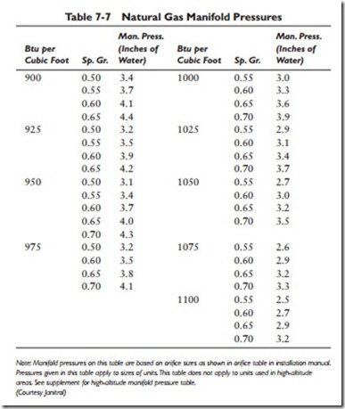
In natural gas-fired duct furnaces, the main burner gas-pressure regulator must be adjusted for the correct gas input. This may be done either by timing the test dial on the meter or by checking the manifold pressure (see Table 7-7). The following steps are recom- mended for adjusting the gas input:
1. Remove the cap on the top of the regulator.
2. Turn the adjusting screw in (or clockwise) to increase the gas input.
3. Back-out the adjusting screw (turn it counterclockwise) to reduce the gas input.
The gas pressure at the inlet to the regulator on natural gas-fired duct furnaces should not be allowed to exceed 12 inches of water.
Propane gas-fired units must maintain a manifold pressure of 11 inches of water for proper operation. These units are not supplied with appliance gas-pressure regulators.
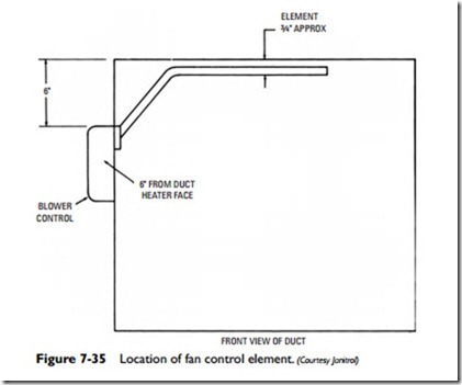
Some duct furnace installations require the use of a fan control. When this is the case, the element of the fan control should be located as shown in Figure 7-35. Adjust the fan control for an off temperature as low as possible without causing the occupants to experience a feeling of cold air.
A proper maintenance schedule for duct furnaces will increase the life of the equipment and result in more efficient and economical
operating characteristics. Frequently check burners, pilot, and the interior and exterior of the heat exchanger for a buildup of residue. Clean the exterior of the heat exchanger with a brush, compressed air, or a heavy-duty vacuum. The following steps are recommended for the more complicated procedure of cleaning the interior of the heat exchanger:
1. Disconnect the flue pipe from the unit.
2. Remove the pilot and burners.
3. Remove the flue collector and heat exchanger tube baffles.
4. Brush the interior of the heat exchanger with a flexible 11⁄2- inch-diameter bristle brush.
5. Remove debris with a vacuum.
6. Replace parts in reverse order to which they were removed.
On a gas-fired duct furnace, leave the pilot on during the summer (except when the unit is part of an air-conditioning system). Inspect the flue pipe for deterioration at the beginning of the heat- ing season. Make a similar inspection of the heat exchanger (and related components) for carbon deposit, rust, or corrosion. Clean or replace when required.
Never light the pilot on gas-fired duct furnaces until you have first read the lighting instructions on the unit plate. Select and maintain a thermostat setting that provides adequate comfort. Do not keep changing the thermostat setting. It will only result in higher heating costs.
