NEW DEVELOPMENTS
All-metal towers with housing, fans, fill, piping, and structural members made of galvanized or stainless steel are now being built. Some local building codes are becoming more restrictive with respect to fire safety. Low maintenance is another factor in the use of all-metal towers.
Engineers are beginning to specify towers less subject to deterioration due to environmental conditions. Thus, all-steel or all-metal towers are called for. Already, galvanized-steel towers have made inroads into the air-conditioning and refrigeration market. Stainless-steel towers are being specified in New York City, northern New Jersey, and Los Angeles. This is due primarily to a polluted atmosphere, which can lead to early deterioration of non-metallic towers and, in some cases, metals.
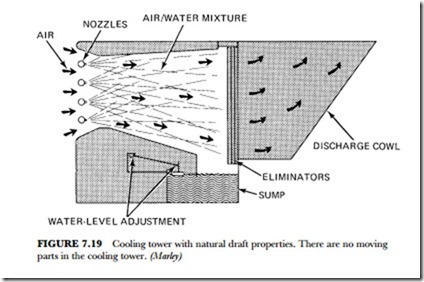
Figure 7.19 shows a no-fans design for a cooling tower. Large quantities of air are drawn into the tower by cooling water as it is injected through spray nozzles at one end of a venturi plenum. No fans are needed. Effective mixing of air and water in the plenum permits evaporative-heat transfer to take place without the fill required in conventional towers.
The cooled water falls into the sump and is pumped through a cooling-water circuit to return for another cycle. The name applied to this design is Baltimore Aircoil. In 1981 towers rated at 10 to 640 tons with 30 to
1,920 gallons per minute were standard. Using prestrainers in the high-pressure flow has minimized the nozzle-clogging problem. There are no moving parts in the tower. This results in very low maintenance costs.
Air-cooled condensers are reaching 1,000 tons in capacity. Air coolers and air condensers are quite attractive for use in refineries and natural-gas compressor stations. They are also used for cooling in industry, as well as for commercial air-conditioning purposes. Figure 7.19 shows how the air-cooled condensers are used in a circuit system that is completely closed. These are very popular where there is little or no water supply.
Temperature Conversion
A cooling tower is a device for cooling a stream of water. Evaporating a portion of the circulating stream does this. Such cooled water may be used for many purposes, but the main concern here is its utilization as a heat sink for a refrigeration-system condenser. A number of types of cooling towers are used for industrial and commercial purposes. They are usually regarded as a necessity for large buildings or manufacturing processes. Some of these types have already been mentioned, but the following will bring you more details on the workings of cooling towers and their differences.
Cooling-water concerns must be addressed for the health of those who operate and maintain the systems. There is the potential for harboring and growth of pathogens in the water basin or related surface. This may occur during the summer and also during idle periods. When the temperature falls to the 70 to 120 degrees F range, there are periods when the unit will not be operational and will sit idle. Dust from the air will settle in the water and create an organic medium for the culture of bacteria and pathogens. Algae will grow in the water—some need sunlight, others grow without. Some bacteria feed on iron. The potential for pathogenic culture is there, and cooling-tower design should include some kind of filtration and/or chemical sterilization of the water.
Types of Towers
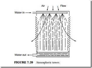
The atmospheric type of tower does not use a mechanical device, such as a fan, to create air flow through the tower. There are two main types of atmospheric towers—large and small. The large hyperbolic towers are equipped with “fill” since their primary applications are with electric power plants. The steam-driven alternator has very high-temperature steam to reduce to water or liquid state.
Atmospheric towers are relatively inexpensive. They are usually applied in very small sizes. They tend to be energy-intensive because of the high spray pressures required. The atmospheric towers are far more affected by adverse wind conditions than are other types. Their use with systems requiring accurate, depend- able cold-water temperatures is not recommended (see Figure 7.20).
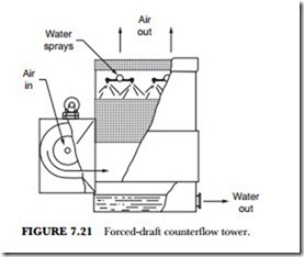
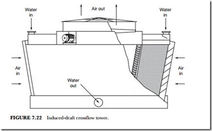
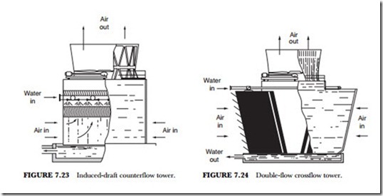
Mechanical draft towers, such as the one shown in Figure 7.21, are categorized as either forced-draft or induced-draft towers. In the forced-draft type the fan is located in the ambient airstream entering the tower. The air is also brought through or induced to enter the tower by a fan above, as in Figures 7.21 and 7.22. In the latter type air is drawn through the tower by an induced draft.
Forced-draft towers have high air-entrance velocities and low edit velocities. They are extremely susceptible to recirculation and are therefore considered to have less performance stability than induced-draft towers. There is concern in northern climates as the forced-draft fans located in the cold entering ambient airstream can become subject to severe icing. The resultant imbalance occurs when the moving air, laden with either natural or recirculated moisture, becomes ice.
Usually forced-draft towers are equipped with centrifugal blower-type fans. These fans require approximately twice the operating horsepower of propeller-type fans. They have the advantage of being able to operate against the high static pressures generated with ductwork. So equipped, they can be installed either in- doors or within a specifically designed enclosure that provides sufficient separation between the air intake and discharge locations to minimize recirculation. (See Figure 7.23.)
Cross flow Towers
Cross flow towers, as seen in Figure 7.24, have a fill configuration through which the air flows horizontally. That means that it is across the downward fall of the water. The water being cooled is delivered to hot wa- ter inlet basins. The basins are located above the fill areas. The water is distributed to the fill by gravity through metering orifices in the basins’ floor. This removes the need for a pressure-spray distribution sys- tem. and it places the resultant gravity system in full view for maintenance.
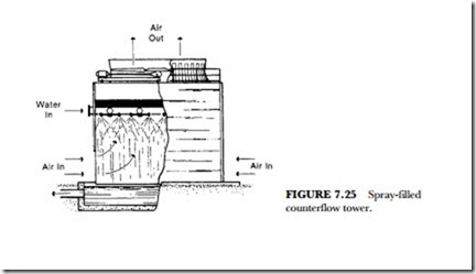
A cooling tower is a specialized heat exchanger (see Figure 7.25). The two fluids, air and water, are brought into direct contact with each other to effect the transfer of heat. In the spray-filled tower, as in Figure 7.25, this is accomplished by spraying a flowing mass of water into a rain-like pattern. Then an upward- moving mass flow of cool air is induced by the action of the fan.
Fluid Cooler
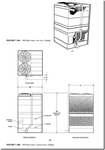
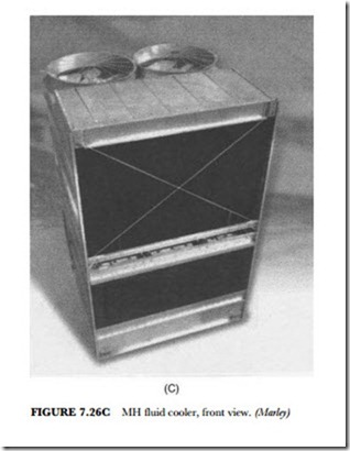
The fluid cooler is one of the most efficient systems for industrial and HVAC applications (see Figure 7.26). By keeping the cooling process fluid and in a clean, closed loop it combines the function of a cooling tower and a heat exchanger into one system. It is possible to provide superior operational and maintenance benefits.
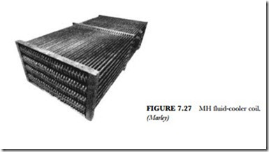
The fluid-cooler coil is suitable for cooling water, oils, and other fluids. It is compatible with most oils and other fluids when the carbon-steel coil is in a closed, pressurized system. Each coil is constructed of continuous steel tubing, formed into a serpentine shape and welded into an assembly (see Figure 7.27). The com- plete asssembly is then hot-dipped in liquid tin to galvanize it after fabrication. The galvanized-steel coil has proven itself through the years. Paints and electrostatically applied coatings cannot seem to approach galvanization for inceasing coil longevity. The coils can also be made of stainless steel.
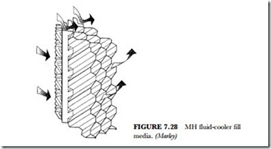
The fluid cooler uses a mechanically induced-draft, crossflow technology. The fill media is located above the coil. The process fluid is pumped internally through the coil. Recirculating water is cooled as it passes over
the fill media (see Figure 7.28). The process fluid is thermally equalized and redistributed over the outside of the coil. A small portion of recirculating water is evaporatd by the drawn air that is passing through the coil and fill media. This cools the process fluid. The coil section rejects heat through evaporative cooling. This process uses the fresh airstream and precooled recirculating spray water. Recirculated water falls from the coil into a collection basin. From the basin it is then pumped back up to be distributed over the fill media.
For industrial and HVAC applications this is an ideal type of system. The process fluid is kept in a clean, closed loop. It combines the function of a cooling tower and a heat exchanger into one system. This im- proves efficiency and has many maintenance benefits. The unit shown here has a capacity ranging from 100 tons to 650 tons in a compact enclosure. It is suitable for cooling a wide range of fluids from water and glycols to quench oils and plating solutions.
