Developing Wiring Diagrams
In this unit, two schematic diagrams are discussed, including their operation and development into wiring diagrams. Developing a wiring diagram from a schematic is the same basic procedure that is followed when installing a control system. Under- standing this process is also a great advantage when troubleshooting existing circuits.
DEVELOPING CIRCUIT 1
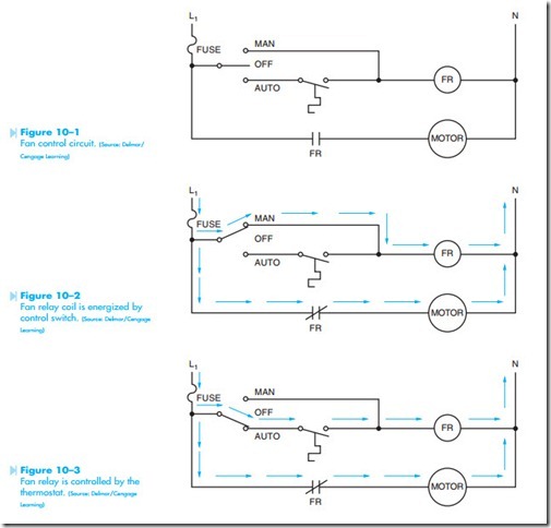
The first circuit discussed is shown in Figure 10–1. In this circuit, a fan motor is controlled by relay FR (fan relay). The circuit is so designed that a switch can be used to turn the circuit completely off, operate the fan manually, or permit the fan to be operated by a thermostat. If the control switch is moved to the “MAN” position as shown in Figure 10–2, a complete circuit is provided to the
Fan relay coil is energized by control switch. (Source: Delmar/Cengage Learning) fan relay coil. Then the relay energizes, FR contact closes and connects the motor to the line. This set- ting permits the fan to be operated at any time, regardless of the condition of the thermostat.
If the control switch is moved to the “AUTO” position as shown in Figure 10–3, the fan will be controlled by the action of the thermostat. When the temperature increases to a predetermined level, the thermostat contact will close. This completes a circuit to FR coil. When FR coil energizes, the FR contact closes and connects the fan motor to the line. When the temperature decreases sufficiently, the thermostat contact opens and breaks the circuit to FR coil. When FR coil deenergizes, FR contact opens and disconnects the motor from the line.
This schematic will now be developed into a wiring diagram. To aid in the connection of this circuit, a simple numbering system will be used. To use
this numbering system, the following rules will be L1 N followed:
1. All components connected to the same line will receive the same number. 1 5
2. Any time a component is gone through, the 2 1 number will change.
3. A set of numbers can be used only once.
Figure 10–4 shows the numbers placed on the schematic. Notice that a 1 is placed at the incoming power line and a 1 is also placed at one side of the fuse. Because the fuse is a component, the number must change on the other side of it. There-fore, the fuse has a 2 on the other side. There is also a 2 placed beside the common terminal of the OFF-MANUAL-AUTOMATIC switch, and a 2 placed beside one side of FR contact. Notice that all of these components have the same number because there is no break between them.
The AUTO side of the switch has been numbered 3, and one side of the thermostat has also been numbered 3. The other side of the thermostat is numbered 4, the MAN side of the switch is number 4, and one side of FR coil is numbered 4. The other side of the coil has been numbered 5, the neutral line is numbered 5, and one side of the motor is numbered 5. The other side of the motor is numbered 6, and the other side of FR contact is numbered 6.
Notice that all the points that are electrically connected together have the same number. Notice also that no set of numbers was used more than once.
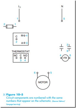
The components of the system are shown in Figure 10–5. Notice that numbers have been placed beside certain components. These numbers Circuit components are numbered with the same numbers that appear on the schematic. (Source: Delmar/ Cengage Learning) correspond to the numbers in the schematic. For example, the fuse in the schematic is shown with a 1 on one side and a 2 on the other side. The fuse in the wiring diagram is shown with a 1 on one side and a 2 on the other side. Notice the OFF- MANUAL-AUTOMATIC switch shown on the schematic. The common terminal is numbered 2, the
MAN terminal is numbered 4, and the AUTO terminal is numbered 3. Now notice the same switch on the wiring diagram. The common terminal is numbered 2, the MAN terminal is numbered 4, and the AUTO terminal is numbered 3. The thermostat in the schematic has been numbered 3 on one terminal and 4 on the other terminal. The thermostat shown in the wiring diagram has three terminals. One terminal is common, one terminal is marked NC, and the other terminal is marked NO. This is a common arrangement for many control components. This shows that the thermostat is a single- pole double-throw switch. Because the thermostat shown in the schematic is normally open, the 3 will be placed beside the common terminal, and the 4 will be placed beside the NO contact. Notice that one of the contacts on FR relay is numbered 2 on one side and 6 on the other side. FR coil is numbered 4 on one side and 5 on the other. One motor terminal is numbered 5 and the other is numbered 6.
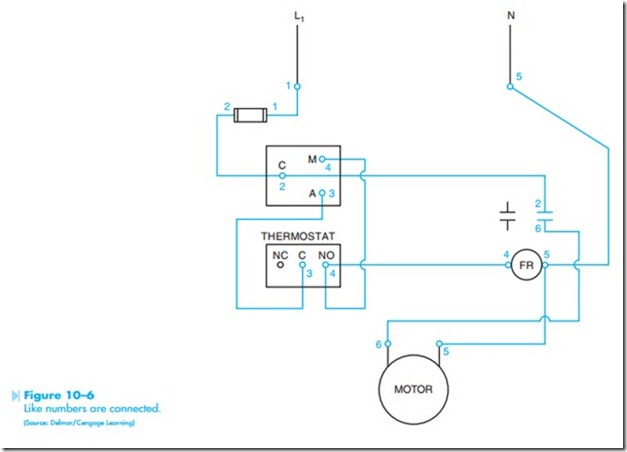
Now that the component parts have been numbered with the same numbers as those used on the schematic, connection can be made easily and quickly. To connect the circuit, connect all the like numbers. For example, all the number 1s will connect together, all the number 2s will connect together, and so forth. The connected circuit is shown in Figure 10–6.


