Chillers
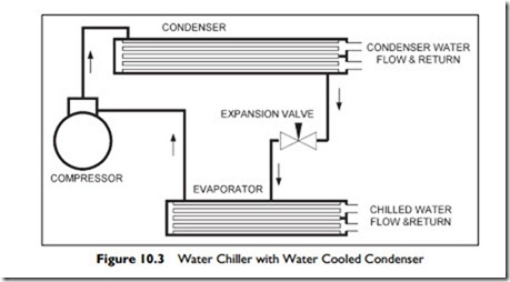
Shown in Figure 10.3, is fundamentally the same as the basic refrigeration circuit you were introduced to in Figure 6.3, Chapter 6, Section 6.3 except that, instead of the evaporator and condenser being air-cooled, they are now water-cooled.
As you can see in the drawing, there are two flows of water, labeled the chilled water and the condenser water. The water that flows through the evaporator coil gives up heat, and becomes cooler. The cooled water is referred to as “chilled water.” The water that flows through the condenser, called the “condenser water,” becomes warmer and is piped away to a cooling tower to be cooled before returning to the condenser to be warmed again.
The size of the cooling load determines the requirements for chiller capacity. This requirement can be met by one or more chillers. The standard measure of chiller capacity is the ton, a heat absorption capacity of 12,000 Btu per hour. The historical origin of this unit is from the early days of refrigeration, when ice production was the main use. In 24 hours, 12,000 Btu per hour produces one ton (2,000 pounds) of ice. Residential air-conditioners are typically one to three tons; central chillers, delivered as complete, preassembled packages from the factory, can be as large as 2,400 tons; and built-up units can go up to 10,000 tons.
The main difference between chillers is the type of compressor:
Smaller compressors are often reciprocating units, very much like an auto- mobile engine, with pistons compressing the refrigerant.
Larger units may have screw or scroll compressors. These compressors are called “positive-displacement,” since they have an eccentric scroll or screw that traps a quantity of refrigerant and squeezes it into a much smaller volume as the screw or scroll rotates.
Finally, for 75 tons up to the largest machines, there is the centrifugal compressor. It has a set of radial blades spinning at high speed that compress the refrigerant.
The choice of compressors is influenced by efficiency at full and part load, ability to run at excess load, size, and other factors. At times of lower load, the capacity of the reciprocating compressor can be reduced in steps by unloading cylinders. The other types of machine can all have their capacity reduced, to some degree, by using a variable speed drive. In addition, the centrifugal machine has inlet guide vanes that reduce the capacity down to below 50%.
When designing a central plant, it is often worth some additional investment in plant and space to have two 50% capacity chillers instead of a single chiller for the following reasons:
There is 50% capacity available in case of a chiller failing.
The starting current is halved, lowering the demands on the electrical system.
Chiller efficiency is higher, the higher the load on the chiller. When load is lower, the second chiller can be turned off.
Maintenance work can be carried out during the cooling season during times of low load.
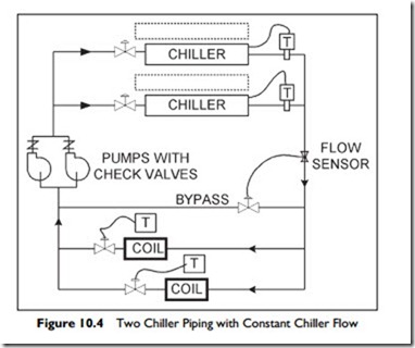
A variable chilled water flow arrangement is shown in Figure 10.4. The chillers are shown with the condensers dotted, since they are not relevant to the chilled water circuit.
As you can see in the diagram, at full load, both chillers and pumps are running, and the valves in the coil circuits are fully open. As the load decreases, the temperature sensors, in front of each coil, start to close their valve, restricting the flow through the coil. The flow sensor, in the chilled-water pipe from the chillers, senses the flow reduction, and restores flow by opening the bypass valve to maintain chiller flow.
When the load drops below 50%, one of the chillers and pumps can switch off, leaving one pump and one chiller to serve the load. The check valve in front of the pump that is “off” closes, to prevent the chilled water from flowing back through it. The output of each chiller is adjusted to maintain the chilled water set-point temperature. As the cooling load on the two coils drops, the return- water temperature will fall and the chiller will throttle back to avoid over-cooling the chilled water.
Load estimation is quite accurate nowadays, so chillers should be sized to match the estimated load without a ‘safety’ factor. This is particularly important where there is just one chiller, since it has to handle all load requirements, including low load. If the chiller is a little undersized, there will be a few hours more a year when the chilled water temperature will drift up a bit. This is generally far better than over-sizing. Over-sizing costs more in chiller purchase price, larger pumps, and other components. The larger chiller will have a lower operating efficiency, so it will have a higher operating and maintenance cost, as well as more difficulty dealing with low loads.
If failure to meet the load is critical, such as in some manufacturing operations, then the issue of sizing to the load is combined with the issue of having standby
capacity for a failed machine. In this case the manufacturing operation should have two units sized to 50% of the load each, with a third 50% unit as standby.

