Stall and surge phenomena in compressors
A noticeable feature of any compressor performance map, such as Figure 5.8, is the surge line. This line denotes the limit to stable operation, and it is traditionally referred to as a surge line, even though the instability that occurs may be surge or stall. It can be reached by reducing the mass flow (with a throttle valve), whereas the rotational speed is maintained constant.
When a compressor goes into surge the effects are usually quite dramatic. Generally, an increase in noise level is experienced, indicative of a pulsation of the air flow and of mechanical vibration. Commonly, a small number of predominant frequencies are superimposed on a high background noise. The lowest frequencies are usually associated with what is termed a Helmholtz-type of resonance of the flow through the machine, with the inlet and/or outlet volumes. The higher frequencies are known to be due to rotating stall and are of the same order as the rotational speed of the impeller.
Rotating stall is a phenomenon of axial compressor flow that has been the subject of many detailed experimental and theoretical investigations. An early detailed survey of the phenomenon was given by Emmons, Kronauer, and Rocket (1959). Briefly, when a blade row (usually the rotor of a compressor) reaches the “stall point,” the blades, instead of all stalling together as might be expected, stall in separate patches and these stall patches, moreover, travel around the compressor annulus (i.e., they rotate).
The stall patches must propagate from blade to blade has a simple physical explanation. Consider a portion of a blade row, as illustrated in Figure 5.13, to be affected by a stall patch. This patch must cause a partial obstruction to the flow that is deflected on both sides of it. Thus, the incidence of the flow onto the blades on the right of the stall cell is reduced, but the incidence to the left is increased. As these blades are already close to stalling, the net effect is for the stall patch to move to the left; the motion is then self-sustaining.
There is a strong practical reason for the wide interest in rotating stall. Stall patches traveling around blade rows load and unload each blade at some frequency related to the speed and number of the patches. This frequency may be close to a natural frequency of blade vibration and there is clearly a need for accurate prediction of the conditions producing such a vibration. Several cases of blade failure due to resonance induced by rotating stall have been reported, usually with serious consequences to the whole compressor.
It is possible to distinguish between surge and propagating stall by the unsteadiness, or otherwise, of the total mass flow. The characteristic of stall propagation is that the flow passing through the annulus, summed over the whole area, is steady with time; the stall cells merely redistribute the flow over the annulus. Surge, on the other hand, involves an axial oscillation of the total mass flow, a condition highly detrimental to efficient compressor operation.
The point a compressor enters stall or surge still cannot be predicted reliably, even with the most advanced computational methods. However, the understanding of the mechanisms leading to stall and surge have been improved significantly through extensive research.
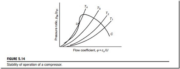
One early physical explanation of the breakdown of the flow in a compressor is given by Horlock (1958). Figure 5.14 shows a constant rotor speed compressor characteristic (C) of pressure ratio plotted against flow coefficient. A second set of curves (T1, T2, etc.) are superimposed on this figure showing the pressure loss characteristics of the throttle for various fixed throttle positions. The intersection of curves T with compressor curve C denotes the various operating points of the combination. A state of flow stability exists if the throttle curves at the point of intersection have a greater (positive) slope than
the compressor curve. That this is so may be illustrated as follows. Consider the operating point at the intersection of T2 with C. If a small reduction of flow should momentarily occur, the compressor will produce a greater pressure rise and the throttle resistance will fall. The flow rate must, of necessity, increase so that the original operating point is restored. A similar argument holds if the flow is temporarily augmented, so that the flow is completely stable at this operating condition.
If, now, the operating point is at point U, unstable operation is possible. A small reduction in flow will cause a greater reduction in compressor pressure ratio than the corresponding pressure ratio across the throttle. As a consequence of the increased resistance of the throttle, the flow will decrease even further and the operating point U is clearly unstable. By inference, neutral stability exists when the slopes of the throttle pressure loss curves equal the compressor pressure rise curve.
Tests on low-pressure ratio compressors appear to substantiate this explanation of instability.
However, for high rotational speed multistage compressors this argument does not seem sufficient to describe surging. With high speeds no stable operation appears possible on constant speed curves of positive slope and surge appears to occur when this slope is zero or even a little negative. A more complete understanding of surge in multistage compressors is possible only from a detailed study of the individual stages’ performance and their interaction with one another.
Casing treatment
It was discovered in the late 1960s that the stall of a compressor could be delayed to a lower mass flow by a suitable treatment of the compressor casing. Given the right conditions this can be of great benefit in extending the range of stall-free operation. Numerous investigations have since been carried out on different types of casing configurations under widely varying flow conditions to demonstrate the range of usefulness of the treatment.
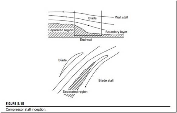
Greitzer, Nikkanen, Haddad, Mazzawy, and Joslyn (1979) observed that two types of stall could be found in a compressor blade row, namely, “blade stall” and “wall stall.” Blade stall is, roughly speaking, a 2D type of stall where a significant part of the blade has a large wake leaving the blade suction surface. Wall stall is a stall connected with the boundary layer on the outer casing.
Figure 5.15 illustrates the two types of stall. Greitzer et al. found that the response to casing treatment depended conspicuously upon the type of stall encountered.
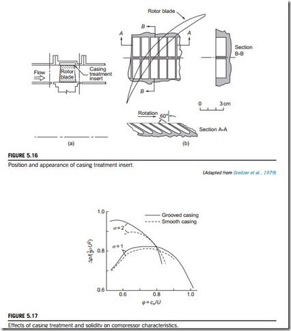
The influence of a grooved casing treatment on the stall margin of a model axial compressor rotor was investigated experimentally. Two rotor builds of different blade solidities, σ (chord- space ratio), but with all the other parameters identical were tested. Greitzer et al. emphasized that the motive behind the use of different solidities was simply a convenient way to change the type of stall from a blade stall to a wall stall and that the benefit of casing treatment was unrelated to the amount of solidity of the blade row. The position of the casing treatment insert in relation to the rotor blade row is shown in Figure 5.16(a) and the appearance of the grooved surface used is illustrated in Figure 5.16(b). The grooves, described as “axial skewed” and extending over the middle 44% of the blade, have been used in a wide variety of compressors.
As predicted from their design study, the high-solidity blading (σ 5 2) resulted in the production of a wall stall, while the low-solidity (σ 5 1) blading gave a blade stall. Figure 5.17 shows the results obtained for the four conditions tested. The most important difference in performance is the change in the stall point with and without the casing treatment. It can be seen that with the grooved casing a substantial change in the range of φ occurred with the high-solidity blading. However, for the low-solidity blading there is only a marginal difference in range. The shape of the performance curve is also significantly affected for the high-solidity rotor blades, with a substantial increase in the peak pressure rise brought about by the grooved casing treatment.
Casing treatment has not been widely adopted in the aircraft engine industry because of the efficiency penalty that it often causes. Smith and Cumpsty (1984) made an extensive series of experimental investigations to try to discover the cause for this loss in compressor efficiency. At the simplest level, it was realized that the slots provide a route for fluid to pass from the pressure surface to the suction surface allowing a small proportion of the flow to be recirculated. The approaching boundary layer fluid tends to have a high absolute swirl and is, therefore, suitably orientated to enter the slots. Normally, with a smooth wall the high swirl would cause energy to be wasted but, with the casing treatment, the flow entering the slot is turned and reintroduced back into the main flow near the blade’s leading edge with its absolute swirl direction reversed. The reentrant flow has, in effect, flowed upstream along the slot to a lower pressure region.
Control of flow instabilities
Important and dramatic advances have been made in recent years in the understanding and control- ling of surge and rotating stall. Both phenomena are now regarded as the mature forms of the natural oscillatory modes of the compression system (see Moore and Greitzer, 1986). The flow model they considered predicts that an initial disturbance starts with a very small amplitude but quickly grows into a large amplitude form. Thus, the stability of the compressor is equivalent to the stability of these small amplitude waves that exist just prior to stall or surge (Haynes, Hendricks, & Epstein, 1994). Only a few of the many papers written on the understanding of these unstable flows and the application of control to suppress instability are cited here.
Epstein, Ffowcs Williams, and Greitzer (1989) first suggested that surge and rotating stall could be prevented by using active feedback control to damp the hydrodynamic disturbances while they were still of small amplitude. Active suppression of surge was subsequently demonstrated on a centrifugal compressor by Ffowcs Williams, and Huang (1989), also by Pinsley, Guenette, Epstein, and Greitzer (1991) and on an axial compressor by Day (1993). Shortly after this, Paduano et al. (1993) demonstrated active suppression of rotating stall in a single-stage low-speed axial compressor. By damping the small amplitude waves rotating about the annulus prior to stall, they increased the stable flow range of the compressor by 25%. The control scheme adopted comprised a circumferential array of hot wires just upstream of the compressor and a set of 12 individually actuated vanes upstream of the rotor used to generate the rotating disturbance structure required for control. Haynes et al. (1994), using the same control scheme as Paduano et al., actively stabilized a three-stage, low-speed axial compressor and obtained an 8% increase in the operating flow range. Gysling and Greitzer (1995) employed a different strategy using aeromechanical feedback to suppress the onset of rotating stall in a low-speed axial compressor.
Further methods of active and passive control to prevent stall or surge continue to be extensively researched and new technologies, such as microdevices, are being applied to this purpose. However, there is still very limited adoption of control within commercially available compressors and even casing treatment is used in only a few jet engine compressor designs. Further application of these technologies in the future will be realized only if their robustness and reliability can match that of existing compressor components.


