HVAC Contractor’s Cooling Load Estimate
If you are not satisfied with your own cooling load estimate, you should invite several air-conditioning contractors to give their bids. This is particularly true if you are considering a central air-conditioning system. For a central air-conditioning system, each contractor should include the estimated Btu per hour required to cool the structure. Each of the bids should be fairly close in estimated Btu and cost. Your choice will be based largely on availability of replacement parts, the reputation of the local dealer for quick and reliable service, and the estimated Btu output. You will naturally want an air-conditioning system that will efficiently remove the required amount of heat. If this proves to be more expensive than another type, you would be wise to choose the more expensive one because your operating costs will be cheaper over the long run. Any contractor’s bid that shows a wide variation from the others either in cost or estimated Btu required to cool the structure should be regarded with some suspicion. It may simply be an attempt to win the contract. Most reliable bids will be fairly close.
Using the ACCA Design Manuals for Sizing Air-Conditioning Systems
The Air-Conditioning Contractors of America (ACCA) publishes a series of manuals used by contractors to size heating and cooling loads. These manuals are updated regularly to match changes in HVAC technology and construction materials. These manuals are available for purchase from the ACCA web site (or their mailing address) by both members and nonmembers. Check the ACCA listing in Appendix A (“Professional and Trade Associations”).
• Manual J Residential Load Calculation (8th Edition). Manual J provides the contractor with the industry-standard residential load calculation method, required by most building codes around the country. The revised and expanded eighth edition procedures produce improved equipment sizing loads for single-family detached homes, small multiunit structures, condominiums, town houses, and manufactured homes.
• Manual S Residential Equipment Selection. Manual S is an essential companion to Manual J. It describes how to select and size heating and cooling equipment to meet Manual J loads based on local climate and ambient conditions at the building site. Manual S covers sizing strategies for all types of cooling and heating equipment, as well as how to use comprehensive manufacturer’s performance data on sensible, latent, or heating capacity for various operating conditions.
• Manual C What Makes a Good Air-Conditioning System?
Manual C provides an overview of appropriate air-handling characteristics for an efficient and comfortable HVAC system.
• Manual D Residential Duct Systems. Manual D describes the different types of residential duct systems, their selection, and their application. Design criteria for duct systems are included in this manual.
Note
Use the ACCA Manual N for sizing the heating or cooling equipment in commercial or industrial buildings. Typically, these structures are larger than homes, are constructed differently, and have correspondingly greater internal HVAC loads. Using an HVAC load calculation method designed for homes can result in over- sizing or undersizing the HVAC equipment.
Central Air-Conditioning
The term central air-conditioning refers not so much to the method of cooling used in a structure as it does to the type of installation and its location. A central air-conditioning system is one that is generally centrally located in a structure in order to simultaneously serve a number of rooms and spaces.
The following sections describe first the different cooling methods used in central air-conditioning systems and then the various central air-conditioning applications used in homes and light commercial buildings.
Cooling Methods
Central air-conditioning can be accomplished by means of a variety
of different cooling methods. The following are described in this chapter:
1. Evaporative cooling
2. Cold-water coil cooling
3. Gas compression refrigeration
4. Gas absorption refrigeration
5. Thermoelectric refrigeration
6. Cooling with steam
In a majority of air-conditioning installations, and almost exclusively in the smaller horsepower range found in residences and small commercial buildings, the vapor or gas compression method of cooling is used (see Gas Compression Refrigeration).
A comparatively recent entry into the field of residential air-conditioning is thermoelectric refrigeration. This method of cooling is based on the thermocouple principle; the cool air is produced by
the cold junctions of a number of thermocouples wired in series (see Thermoelectric Refrigeration).
Absorption refrigeration and cooling with steam are cooling methods generally found in large commercial and industrial applications (see Gas Absorption Refrigeration and Cooling with Steam).
Evaporative Cooling
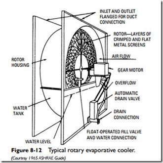
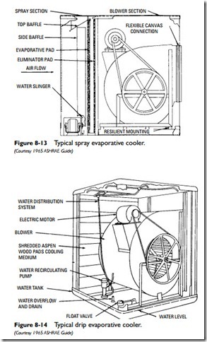
An evaporative cooling system cools the indoor air by lowering its dry-bulb temperature. In effect, it cools by evaporation, and it accomplishes this function by means of an evaporative cooler. Figures 8-12, 8-13, and 8-14 show the basic components of three evaporative coolers.
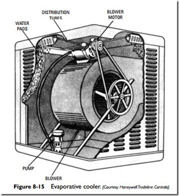
As shown in Figure 8-15, an evaporative cooler consists of a blower and blower motor, water pump, water distribution tubes, water pads, and a cabinet with louvered sides. In operation, the blower draws air through the louvers of the cabinet where it comes into contact with the moisture in the pads. The air passes through these moist water pads and into the interior of the structure.
The water in the pads absorbs heat from the air as it passes through them. This causes a portion of the water to evaporate and lowers the dry-bulb temperature of the air as it enters the room or space. It is this lower dry-bulb temperature that produces the cooling effect.
In an evaporative cooling system, the water is recirculated and used over and over again. Only enough water is added to replace the amount lost by evaporation. The pump supplies water to the pads through the distribution tubes.
The air is never recirculated because it contains too much moisture once it has passed through the evaporative cooler. New air must always be drawn from the outdoors.
An evaporative cooling system is generally not very effective in a humid climate because the outdoor air is not dry enough. Evaporative coolers have been used for years with excellent results in New Mexico, Arizona, Nevada, and similar areas with dry climates.
Cold-Water Coil Cooling
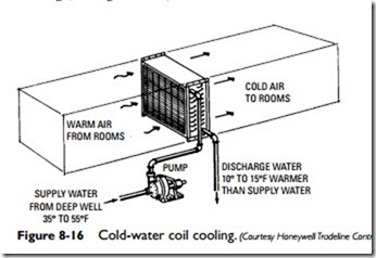
Indoor air temperatures can also be reduced by passing warm room air over a cold surface, such as a water-cooled coil, and then recirculating it back into the room. When a water-cooled coil is used for this purpose, the system is referred to as cold-water coil cooling (see Figure 8-16).
A water-cooled coil is effective only when there is a sufficient sup- ply of cold water. The temperature of the water should range from 35° to 55°F, and the most common source is a deep well. A pump supplies the cold water to the coil where it picks up heat from the air passing through it. This warmer water is then discharged to a storm sewer, dry well, or some other outdoor receiver. The discharge water is approximately 10° to 15°F warmer than the supply water.
Gas Compression Refrigeration
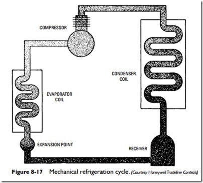
A gas compression refrigeration air-conditioning system operates on the direct-expansion cooling principle. Basically the system consists of a compressor, condenser coil, receiver, expansion device, and evaporator coil. A refrigerant flowing through the system is affected by temperature and pressure acting simultaneously in such a way that heat is transferred from one place to another. In other words, heat is removed from the room air for cooling and added to it for heating.
Mechanical Refrigeration Cycle
The mechanical refrigeration cycle is illustrated schematically in Figure 8-17. The liquid refrigerant is contained initially in the
receiver, which is usually located in the lower section of the con- denser, although it can be a separate tank. The compressor, acting as a pump, forces the liquid refrigerant under high pressure through the liquid line to the expansion device.
The function of the expansion device is to regulate the flow of refrigerant into the evaporator coil. This expansion device may be in the form of an expansion valve or a capillary tube.
As the high-pressure liquid refrigerant is forced through the expansion device, it expands into a larger volume in the evaporator, thus reducing its pressure and consequently its boiling temperature. Under this low pressure, the liquid refrigerant boils until it becomes a vapor. During this change of state, the refrigerant absorbs heat from the warm air flowing across the outside of the evaporator.
After the refrigerant has boiled or vaporized, thus removing its quota of heat, it is of no more value in the evaporator coil and must be removed to make way for more liquid refrigerant. Instead of being exhausted to the outdoor air, the low-pressure heat-laden refrigerant vapor is pumped out of the evaporator through the suction line to the compressor. The compressor then compresses the refrigerant vapor, increasing its temperature and pressure and forces it along to the condenser.
At the condenser, the hot refrigerant vapor is cooled by lower temperature air passing over the condenser coils, thus absorbing some of the refrigerant heat. As a result, the air temperature increases and the refrigerant temperature decreases until the refrig- erant is cooled to its saturation condition. At this condition, the vapor will condense to a liquid. The liquid, still under high pressure, flows to the expansion device, thus completing the cycle.
Note that cold is never created during the mechanical refrigeration cycle. Instead, heat is merely transferred from one place to another. When the refrigerant passes through the evaporator, it absorbs heat from the room air, thereby cooling it. When the higher-temperature refrigerant passes through the condenser, it gives up heat to the air entering the room, thereby warming it.
Gas Absorption Refrigeration
The gas absorption refrigeration method of cooling uses heat as its energy instead of electricity. This heat can be in the form of steam from a gas-fired or oil-fired atmospheric steam generator, or it can come from a gas or oil burner applied directly to the refrigeration generator. Normally, water is used as the refrigerant and lithium bromide as an absorbent. The absorption unit operates under a vacuum that gives the water a boiling temperature low enough for comfort cooling.
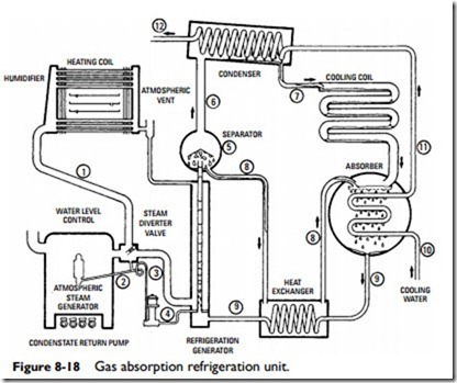
The absorption refrigeration system shown in Figure 8-18 is charged with lithium bromide and water, the lithium bromide being the absorbent and the water the refrigerant. This solution is contained within the refrigeration generator.
As steam heat is applied to the generator, a part of the refrigerant (water) is evaporated or boiled out of the solution. As this water vapor is driven off, absorbent solution is raised by vapor lift action to the separating chamber (5) above the generator.
Refrigerant (water) and absorbent separate in the vapor separating chamber (5), the refrigerant vapor rises to the condenser (6), and the separated absorbent solution flows down through a tube (8) to the liquid heat exchanger and thence to the absorber.
The refrigerant (water vapor) passes from the separating chamber to the condenser through a tube (6), where it is condensed to a liquid by the cooling action of water flowing through the condenser tubes. The cooling water that flows through the condenser is brought from some external source, such as a cooling tower, city main, or well.
The refrigerant vapor thus condensed to water within the con- denser then flows through a tube (7) into the cooling coil. This tube contains a restriction that offers a resistance and therefore a pressure barrier to separate the slightly higher absolute pressure in the condenser from the lower pressure within the cooling coil. The refrigerant (water) entering the cooling coil vaporizes due to the lower absolute pressure (high vacuum) that exists within it. The high vacuum within the evaporator lowers the boiling temperature of water sufficiently to produce the refrigeration effect.
The evaporator or cooling coil is constructed with finned horizon- tal tubes, and the air being cooled flows horizontally over the coil surface. Evaporation of the refrigerant takes place within the cooling coil, the heat of evaporation for the refrigerant is extracted from the air stream, and cooling and dehumidifying are accomplished.
In the absorber, the solution absorbs the refrigerant vapors that were formed in the evaporator directly adjacent. To explain the presence of the absorbent at this point, it is necessary to divert attention back to the generator. The absorbent was separated from the refrigerant by boiling action. The absorbent then drains from
the separator (5) down to the liquid heat exchanger and then to the absorber through the tube (8) designed for this purpose. The flow of solution in this circuit can actually exist by gravity action only because the absorber is slightly below the level of the separating chamber.
It must be understood at this point that lithium bromide in either dry or solution form has a very strong affinity for water vapor. It is because of this principle that the refrigerant vapor is absorbed back into solution again. Because the rate of absorption is increased at lower temperatures, a water-cooling coil is provided within the absorber shell.
The resultant mixture of refrigerant and absorbent drains back through the heat exchanger through another tube (9) to the refrigeration generator where it is again separated into its two component parts to repeat the cycle.
The liquid heat exchanger serves to increase operating efficiency. The absorbent solution leaves the refrigeration generator at a relatively high temperature. Because its affinity for water vapor is increased as its temperature is reduced, precooling is desirable before it enters the absorber. Conversely, the combined solution of refrigerant and absorbent leaving the absorber and flowing toward the generator is relatively cool.
Because heat is applied in the generator to drive off water vapor, it is desirable to preheat this liquid before it enters the generator. With counterflow action in the liquid heat exchanger, both precooling and preheating are accomplished within the solution circuit.
As stated previously, a high vacuum exists throughout all circuits. However, a slightly higher absolute pressure exists in the gen- erator and condenser than in the cooling coil and absorber. This difference in pressure is maintained by a difference in height of the solution columns (or restrictor) in the various connecting tubes.
The effect of heat applied to the refrigeration generator raises the absorbent solution to the vapor separator located at the top of the generator. The absorbent solution is able to flow from the generator to the absorber by gravity, aided by the slight pressure differential between the two chambers.
In the absorber, water vapor is taken into the solution, which then flows back to the bottom of the generator. Because the pressure in the absorber is slightly below that in the generator, solution flow from a low-pressure area to one of relatively higher pressure is accomplished by the higher elevation of the absorber.
The water vapor (refrigerant) released from the generator rises to the condenser, where it is condensed to a liquid. Elevation of the condenser permits gravity flow of the refrigerant to the evaporator, aided by the slight pressure differential between the two chambers. Thus, by taking advantage of differences in fluid temperatures, density, and height of columns, continuous movement in the same direction throughout all circuits is accomplished without moving parts.
The cooling-water circuit can be traced in Figure 8-18 by noting that it enters the absorber coil at point 10. Flow is then directed through tube 11 to the condenser and leaves the unit at point 12.
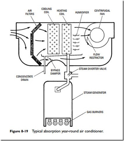
cleaned, passes through the cooling coil (evaporator) and heating coil, and is then returned to the rooms or spaces being cooled.
During the cooling cycle, the room air is cooled and dehumidified. Heat is extracted from the air and moisture is condensed on the cooling coil. Thus, both functions of cooling and dehumidification are performed simultaneously. During the heating cycle, the air is warmed by the steam heating coil, and moisture is added by the humidifier.
Steam is provided for both heating and cooling cycles by the steam generator located in the base of the conditioner. Steam at atmospheric pressure flows from the generator into a two-position steam diverter valve, which automatically directs the flow of steam to either the heating coil or the absorption refrigeration unit. The steam diverter valve is positioned by an electric motor governed by a remote heating and refrigeration switch.
After the air leaves the heating coil, it passes through the humid- ifier, which functions during the heating cycle only. The humidifier, in this installation, consists of a number of horizontal trays, each equipped with an overflow tube that feeds water to the next lower tray. This arrangement provides a large evaporative surface for positive humidification. Water is supplied at a predetermined and controlled rate of flow to the humidifier trays.
The air is drawn through the unit by a centrifugal fan that delivers the heated or cooled air through a duct-distributing system to the various rooms or spaces being conditioned. Because less air is normally required for winter heating than for summer cooling, a flow-restricting device is mounted in the fan scroll and functions on the heating cycle to automatically reduce the flow of air by adding resistance. This device usually consists of a pivoted blade, and its location is indicated by the dotted line in Figure 8-19.
When maximum air delivery is desired, the air-restricting device is positioned tightly against the inside column of the fan scroll. When the restrictor is pivoted toward the fan wheel, thereby reducing normal wheel clearance, a resistance is thus imposed which alters fan performance to reduce air delivery. The airflow-restricting device is moved automatically between predetermined summer and winter positions by the motor that governs its operation.
Correct air distribution practices dictate a need in some cases for the handling of a greater quantity of air on the cooling cycle than required by the refrigeration unit for full-rated cooling capacity. Should this excess air be needed, the amount in excess of rated quantity should be handled through the bypass, thus ensuring correct cooling coil performance. The bypass damper is located in the air circuit just beyond the cooling coil. During the heating season, the bypass damper will automatically be repositioned by the con- trolling motor to the closed position.
Thermoelectric Refrigeration
Thermoelectric refrigeration is a cooling method developed comparatively recently for use in residential air-conditioning, although the operating principle is not new. Thermoelectric refrigeration has been used for years as a cooling method for small refrigerators. It is also the cooling used on nuclear submarines.
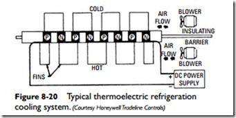
Thermoelectric refrigeration is based on the thermocouple principle. In a thermoelectric refrigeration cooling system, electricity in the form of direct current power is applied to the thermocouple and heat is produced. The heat is transferred from one junction to the other producing a hot and cold junction. The direction of current flow determines which junction is hot and which is cold. If the power supply connections are reversed, the positions of the hot and cold junctions are also reversed.
The amount of cooling or heating that can be produced with a single thermocouple is small. For that reason, a number of thermo- couples are wired in a series to produce the quantity of heating and cooling required by the installation.
The schematic of a typical thermoelectric cooling system shown in Figure 8-20 illustrates how direct current power is applied to a number of thermocouples wired in series. Heat is transferred from one side to the other depending on the direction of current flow.
Cooling with Steam
Cooling with steam is based on the well-known fact that the boiling point of any liquid depends on the pressure to which it is subjected. By lowering the pressure, the boiling point is also lowered. When a liquid at a certain temperature and corresponding boiling point is
sprayed into a closed vessel in which the pressure is lower, the entering liquid is above its boiling point at the new reduced pressure, and rapid evaporation takes place.
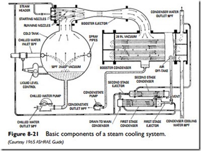
The basic components of a typical steam cooling system are shown in Figure 8-21. In operation, the water to be cooled, returning from the air-conditioning or other heat-exchanging apparatus at a temperature of 50°F, is sprayed into the evaporator. Because of the large surface of the spray, the boiling (or flashing) is very rapid and the unevaporated water falls to the bottom of the evaporator chilled to 40°F. At this temperature it is withdrawn from the evaporator by the chilled water pump and pumped to the heatexchanging apparatus to again absorb heat, thus completing the cycle.
In the booster ejector, steam flowing at high velocity through nozzles located in the ejector head is expanded in the venturishaped diffuser. The kinetic energy of the steam is in part utilized in imparting velocity to the water vapor liberated in the evaporator and in compressing this vapor over a compression range from the evaporator pressure to the condenser pressure. In this compression, the temperature of the water vapor is raised so that it can be readily condensed by condensing water at temperatures normally available.
The initial evacuation and constant purging of air and other noncondensable gases is handled by a secondary group of ejectors and condensers. These are relatively small in size, but of the greatest importance, and normally consist of two steam-operated ejectors in series, each with its own condenser in which condensing water condenses the propelling water and entrained vapor. Condensers used in a steam cooling system may be either of the surface type, with water passing through condenser tubes over which the mixture of operating steam and water vapor flows, or of the jet or barometric type, with condensing water sprayed directly into the steam mixture.
The amount of condensing water and condensing surface employed is such that the vapor temperature in the condenser is normally 5°F above the condensing water discharge temperature. This fixes the terminal pressure condition to which the steam mixture is compressed. The initial pressure condition (in the evaporator) is determined by the chilled water temperature desired. Variation in either of these two conditions affects the compression range and therefore the amount of operating steam required.
