Performance Lights
Most electronic air cleaners are equipped with performance lights to indicate how the unit is operating. How these lights will be used will depend on the individual manufacturer. Read the manufacturer’s
operating instructions concerning the use of these lights. As the following paragraphs make clear, they are not always used in the same way.
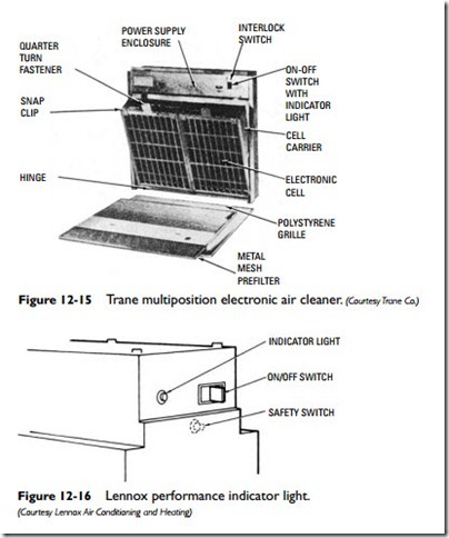
The built-in performance indicator light on the Trane electronic air cleaner shown in Figure 12-15 operates in conjunction with the on-off switch. If the electronic air cleaner is operating correctly, the performance indicator light will be on whenever the system fan is running and the on-off switch is in the on position.
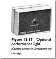
The performance indicator light on the Lennox electronic air cleaner shown in Figure 12-16 glows red when the unit is operating correctly. This light also operates in conjunction with the on-off switch, which must be on. An optional performance light is available with a Lennox electronic air cleaner for installation in the living spaces (see Figure 12-17). It remains off when the unit is operating correctly.
Thermo-Pride electronic air cleaners use both an amber-colored operating light and a red performance light with their units. The
operating light indicates that line voltage is on. The red performance light indicates that the electronic cell is operating properly. Both lights must be on during normal operation.
Sail Switch
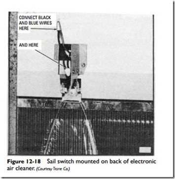
A sail switch (see Figure 12-18) is designed to complete circuit power to auxiliary equipment in a forced warm-air system when the duct air velocity is increased. Consequently, it provides on-off
control of electronic air cleaners, humidifiers, odor-control systems, and other equipment that is energized when the fan is operating.
In operation, the air movement push- ing against the sail actuates the switching device, which then energizes the power supply. Using a sail switch allows the auxiliary equipment to be wired independently of the system blower motor.
The manufacturer’s installation instructions should be carefully read and followed because the sail is installed at the site.
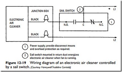
The switch mechanism or sail switch body is mounted on the back of the electronic air cleaner usually before it is installed in the return air duct opening (see Figure 12-18). The sail is mounted on the switch body after installation of the air cleaner to prevent damage of the sail. A typical wiring diagram is shown in Figure 12-19.