WATER PRESSURE REDUCING VALVES
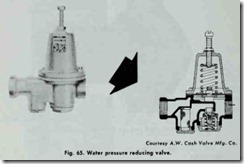
Most forced hot-water heating systems are equipped with a pressure-reducing valve which is designed to automatically feed water into the boiler when the pressure in the system drops below the valve setting. When the pressure returns to the minimum pres sure setting, the valve automatically closes. Thus, the function of a water pressure reducing valve is to keep the system automat ically filled with water at the desired operating pressure (Fig. 65).
These valves are also referred to as pressure reducing boiler feed valves or feed water pressure regulators. Regardless of what they are called, their function remains the same; that is, to deliver water to·:the boiler at the required pressure. To perform this func tion, they are always installed in the cold water supply line. If they are part of a combination pressure reducing and pressure relief valve (dual control), the pressure relief part of the combination valve is always located between the boiler and the pressure re ducing part.
A manually operated feed valve was used on older hot-water heating systems to provide the same function as the automatic water pressure reducing valve. On these older systems, the man ually operated feed valve should be partly opened and water added to the boiler when the movable (white or red) arrow on the alti tude gauge drops below the setting of .the stationary (black) arrow (see ALTITUDE GAUGES in this chapter).
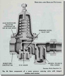
Some pressure reducing valves are equipped with a built in check valve in the supply inlet to prevent a back flow of contam inated boiler water into the domestic water supply. This back flow drainage of boiler water generally occurs when the supply pres sure falls below the feeder valve setting. Not only can this drain age cause possible damage to .the boiler, it can also contaminate the domestic water supply. Some pressure reducing valves are also equipped with integral strainers to trap foreign matter that may clog the valve. The strainer screen should be removed for cleaning at the beginning of each heating season. This can be done by removing -the bottom plug from the strainer and withdrawing the screen. Clean and carefully replace screen and plug.
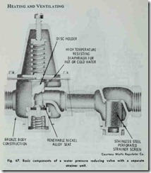
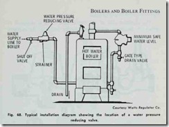
The principal components of a water pressure reducing valve are shown in Fig. 66. This particular valve is constructed with an integral strainer. It is also possible to use separate units in com bination such as Fig. 67 illustrates. The two units are joined by a short threaded connection. A typical installation in which a water pressure reducing valve is used is shown in Fig.68
As was mentioned before, a water pressure reducing valve should be installed in the water supply line to the boiler. It should also be installed at a level above .the boiler and in a horizontal position. Before installing the valve, flush out the supply pipe to clear it of chips, scale, dirt, and other foreign matter that could interfere with its operation. Install a shut-off valve ahead of the regulator and then connect the supply line to the inlet (usually marked IN on the valve casting).
To fill the system, open the shut-off valve located ahead of the pressure reducing valve. Water will flow into the system until it is full and under pressure. The shut-off valve must always be kept open when the system is in operation.
Water pressure reducing valves are usually set by the manu facturer to feed water to the boiler at approximately 15 lbs. pres sure. This pressure setting is sufficient for residences and houses up to a three story building in size. For higher buildings in which the pressure may not be sufficient to lift the water to highest radi ation, it may be necessary to reset the water pressure reducing valve for higher pressure. To do this, calculate the number of feet from the regulator to the top of the highest radiation. Multiply this by .43 and add 3 lbs. This will give the pressure needed to raise the water to the highest radiator and keep it under pressure. Loosen the lock nut on the valve and turn the adjustment screw clockwise slowly until the gauge indicates the pressure calculated. When the desired pressure is obtained tighten the lock nut.
COMBINATION VALVES (DUAL CONTROLS)
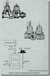
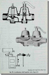
Combination or dual control valves (Figs. 69 and 70) are de signed for use in hot water space heating systems. These valves consist of a pressure reducing and regulating valve, and a positive relief valve contained in one body. Sometimes an integral by-pass valve is also included in the same unit.
The purpose of a combination valve is to provide pressure regulation and safety control, and to reduce boiler pressure and assure automatic filling when conditions warrant. The valve is installed on the supply line of a boiler with the relief valve section closest to the boiler.
The regulator side of the combination valve is designed to reduce the incoming water supply to the boiler to the required 14 lbs. operating pressure for a one, two, or three story house. The pressure in the system builds up due to thermal expansion when the boiler is fired. Under normal operating conditions, the expansion tank will absorb the additional pressure. However, if the expansion tank is water-logged or if the system has no expansian tank, the relief side of the valve will open at 23 psi and drop the pressure back to within safe limits . If the pressure should drop below 14 psi, the regulator will open again and automatically refill the system. A built-in check valve prevents the back flow of contaminated boiler water into the potable boiler water supply.
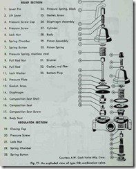
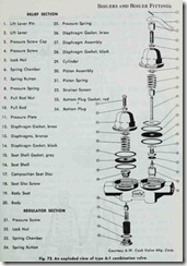
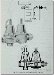
Exploded views of combination valves are shown in Figs. 71 and 72. The Cash-Acme Type CBL Valve (Fig. 73) differs from the other two by having a built in by-pass valve. In all other re spects, it is similar to the others except that it should be installed as close as possible to the top of the boiler (using close nipples). The principal advantages of having the by-pass valve included are:
1. Allows rapid filling of the system.
2. Permits an easy high pressure test for leaks and system purging.
3. Passes first filling dirty water around the valve seat, assur ing a clean, good seating surface.
4. Permits the use of a wide opening, small seated regulator which prevents wire drawing and rapid wearing of the seat.
The most common types of problems encountered when using combination valves are the following:
1. Relief valve drips or cannot be shut off tightly.
2. Boiler pressure rises above the reducing valve setting.
3. Water escaping “weep hole” on top of the regulator.
4. Water escaping feeder side of the combination valve.
5. Foreign matter on the seat of the relief or regulator section of the valve.
Some of the problems listed above (particularly the first two) may not be the fault of the valve itself. For example, a dripping relief valve can be caused by an expansion tank being completely filled up with water; an undersized expansion tank; or a leak in the coil of a tankless or indirect water heat installed in the boiler. These possibilities should be checked before attempting to service or repair the valve. The procedures are outlined in this chapter.
If, by process of elimination, the problem can be traced to the valve, try tapping the side of the valve with a wrench. Some times a piece of foreign matter will become lodged and cause the regulator piston to stick. A sharp tap with a wrench may dislodge it and allow the valve to function properly.
Foreign matter such as dirt, pipe scale, or chips will often cause a valve to malfunction by lodging on a seating surface, or nicking or chipping the surface. Valve manufacturers will often provide replacements, or instructions for field servicing and re pairing. The latter should be attempted only by a skilled and ex perienced worker with the proper tools and gauges.
Water seeping from the regulator “weep hole” or from the feeder side of a combination valve is usually an indication that there is a rupture or leak in the diaphragm. Follow the procedures described in the preceding paragraph for repairing the valve. An occasional flushing of the relief side of a combination valve wi11 reduce the possibility of the type of lime or scale build up that can cause the valve to fuse shut.
