CHIMNEYS
Most chimneys are constructed of brick or metal. If a brick chimney is used, it should be lined with a protective material to prevent damage from water vapor. The most commonly used liner is smooth faced tile. Prefabricated factory built chimneys are also used, but only those listed by Underwriters’ Laboratories are suitable for use with fuel burning equipment.
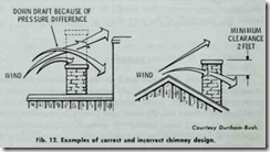
The standard chimney must be at least 3 feet higher than the roof or 2 feet higher than any portion of the structure within 10 feet of the chimney flashing in order to avoid downdrafts (Fig. 12).
An existing chimney should always be checked to make sure it is smoke tight and clean. Any dirt or debris must be cleaned out before the furnace or boiler is used.
TROUBLESHOOTING THE CHIMNEY
The chimney must give sufficient draft for combustion or the furnace will not operate efficiently. It must also provide a means for venting the products of combustion to the outside. Although a chimney produced draft is not as important for the combustion process in gas-fired appliances as it is in other types of fuel burning equipment, the venting capacity of the chimney is extremely im portant. The chimney must be of a suitable area and height to vent all the products of the combustion process.
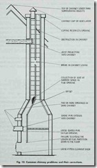
Fig. 13 illustrates some of the common chimney problems that
can cause insufficient draft and improper venting. Some of these problems are detectable by observation; others require the use of a draft gauge.
| Problem | Remedy |
| Top of chimney is lower than surrounding objects | Extend chimney above all objects within 20 feet |
| Chimney cap or ventilator | Remove |
| Coping restricts opening | Make opening as large as inside of chimney |
| Obstruction in chimney | Use rod or weight on string or wire to break and dislodge |
|
Joist projecting into chimney |
Change support for joist so that chimney will be clear. Should be handled by a competent brick contractor |
| Break in chimney lining | Rebuild chimney with a course of brick between flue tiles |
| Collection of soot at narrow space in flue opening |
Clean out with weighted brush or bag of loose gravel on end of line. May be necessary to open chimney |
| Offset | Change to straight or long offset Least important opening must |
| Two or more openings in same chimney | be closed using some other chimney flue. |
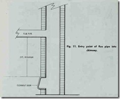
| Smoke pipe extends into chimney | Shorten pipe so that end is flush with inside of tile |
| Loose fitted cleanout door | Leaks should be eliminated by cementing all pipe openings |
| Failure to extend the length of flue partition down to the floor | Extend partition to floor level |
| Loosely fitted cleanout door | Close all leaks with cement |
Sometimes a chimney will be either too small or too large for the installation. When this is the case, the chimney should be rebuilt with the necessary corrections made in its design.
DRAFT HOOD
A gas-fired furnace should be equipped with a draft hood attached to the flue outlet of the appliance. The draft hood used on the appliance should be certified by the American Gas Associa tion. Only gas conversion furnaces equipped with power-type burners and conversion burner installations in large steel boilers with inputs in excess of 400,000 Btu/hr are not required to have draft hoods.
A draft hood is a device used to insure the maintenance of constant low draft conditions in the combustion chamber. By this action, it contributes to the stability of the air supply for the com bustion process. A draft hood will also prevent excessive chimney draft and downdrafts that tend to extinguish the gas burner flame. Because of this last function, a draft hood is often referred to as a draft diverter.
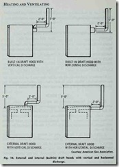
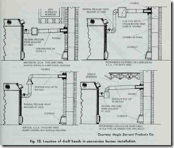
Draft hoods may be either internally or externally mounted depending upon the design of the furnace. Never use an external type draft hood with a furnace already equipped with an internal draft hood. Either vertical or horizontal discharge from the draft hood is possible (Fig. 14). Locations of draft hoods in conversion burner installations are illustrated in Fig. 15.
NEUTRAL PRESSURE POINT ADJUSTER
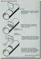
In some installations, a neutral pressure point adjuster is in stalled in the flue pipe between the furnace and the draft hood. The procedure for making a neutral pressure point adjuster is illustrated in Fig. 16. Always leave the neutral pressure poin t adjuster in wide open position until after the burner rating has been established.
BASIC COMPONENTS
The basic components of a gas-fired forced warm-air furnace are:
1. Automatic controls,
2. Heat exchanger,
3. Gas burner,
4. Gas pilot assembly,
5. Blower and motor,
6. Air filter(s).
Each of these components is described in the sections that follow. Additional information is contained in Chapter 10 (FUR NACE FUNDAMENTALS) and the various chapters in which furnace controls and fuel burning equipment are described.
