CIRCUIT OPERATION
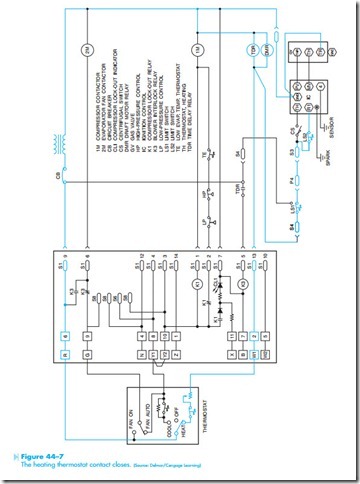
When the heating thermostat contact closes, a circuit exists to the time delay relay (TDR) and draft motor relay (DMR), Figure 44–7. Power is also supplied to the ignition control module. The draft motor controls the centrifugal switch connected to the thermostat input of the ignition control module. Its function is used to insure that gas will not be supplied to the burner unless the draft motor is in operation.
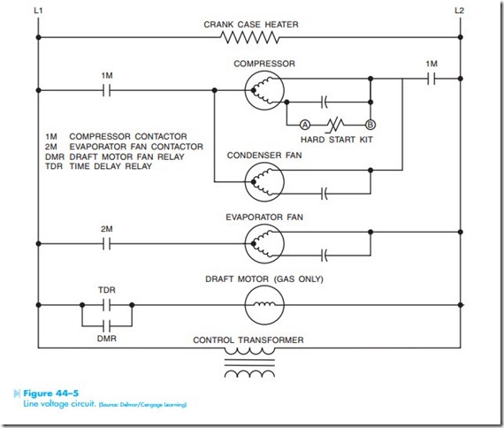
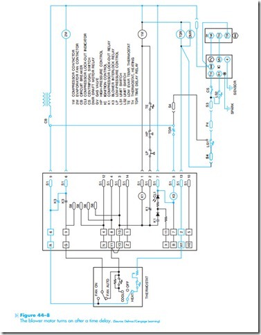
In Figure 44–8, it is assumed that the centrifugal switch has closed and permitted the gas burner to ignite. It is also assumed that the time delay relay has permitted TDR contacts to close. When the TDR contacts close, a current path is provided to the coil of the K3 relay causing all K3 contacts to change position. When the normally open K3 con- tact closes, a current path is provided to the coil of the 2M contactor. When 2M energizes, the blower motor turns on, Figure 44–5. The circuit will continue to operate in this manner until the thermostat contacts reopen.
OPERATION OF THE COMPRESSOR LOCK-OUT RELAY
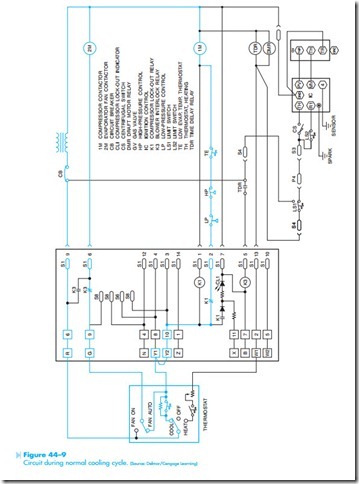
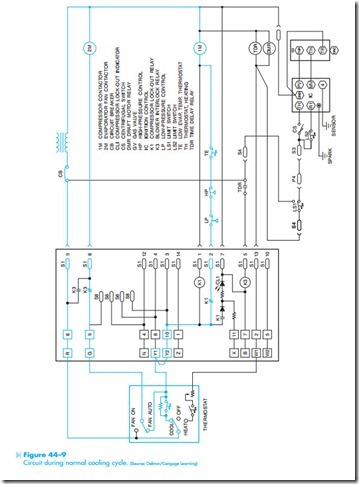
The compressor lock-out relay can operate only when the thermostat is set in the cooling mode. In Figure 44–9 it is assumed that the thermostat has been set for the cooling mode and the thermostat contact is closed. The main current path is through the normally closed K1 contact, low- pressure switch, high-pressure switch, and evaporator temperature switch to the coil of 1M contactor. The current takes this path because of the high impedance of coil K1. When coil 1M energizes, the compressor and condenser fan start, Figure 44–5. There is also a current path through the thermostat fan switch, the normally closed K3 contact and 2M coil. When the 2M coil energizes, the evaporator fan motor starts. The circuit will continue to operate in this manner until the thermostat contact opens or some other problem occurs.
Now assume that the low-pressure switch opens, Figure 44–10. The open circuit caused by the open low-pressure switch now connects coil K1 in series with coil 1M. Because coil K1 has a much higher impedance than 1M, most of the voltage is across K1 and not 1M, causing the K1 relay to energize and the 1M contactor to deenergize. The normally closed K1 contacts open and the normally open K1 contacts close. When the normally open K1 contacts close, a current path is provided to the compressor lock-out indicator. The now open K1 contact prevents the compressor from restarting if the low-pressure switch should reclose. The circuit will remain in this condition until the control power is interrupted.
