ISOLATION TRANSFORMERS
The transformers shown in Figures 19–1 and 19–2 are isolation transformers. This means that the secondary winding is physically and electrically isolated from the primary winding. There is
no electrical connection between the primary and secondary winding. This transformer is magnetically coupled, not electrically coupled. This “line isolation” is often a very desirable characteristic. Because there is no electrical connection between the load and power supply, the transformer becomes a filter between the two. The isolation transformer will greatly reduce any voltage spikes that originate on the supply side before they are transferred to the load side. Some isolation transformers are built with a turns ratio of 1:1. A transformer of this type will have the same input and output voltage and is used for the purpose of isolation only.
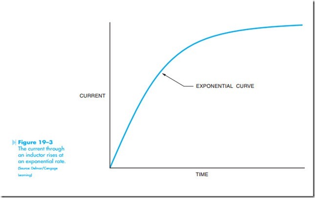
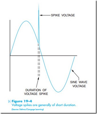
The reason that the transformer can greatly reduce any voltage spikes before they reach the secondary is because of the rise time of current through an inductor. The current in an inductor rises at an exponential rate, Figure 19–3. As the current increases in value, the expanding magnetic field cuts through the conductors of the coil and induces a voltage that is opposed to the applied volt- age. The amount of induced voltage is proportional to the rate of change of current. This simply means that the faster the current attempts to increase, the greater the opposition to that increase will be. Spike voltages and currents are generally of very short duration, which means that they increase in value very rapidly, Figure 19–4. This rapid change of value causes the opposition to the change to increase just as rapidly. By the time the spike has been transferred to the secondary winding of the transformer, it has been eliminated or greatly reduced, Figure 19–5.
Another purpose of isolation transformers is to remove some piece of electrical equipment from ground. It is sometimes desirable that a piece of electrical equipment not be connected directly to ground. This is often done as a safety precaution to eliminate the hazard of an accidental contact between a person at ground potential and the ungrounded conductor. If the case of the equipment should come in contact with the ungrounded conductor, the isolation transformer would prevent a circuit being completed to ground through someone touching the case of the equipment. Many alternating current circuits have one side connected to ground. A familiar example of this is the common
120-volt circuit with a grounded neutral conductor, Figure 19–6. An isolation transformer can be used to remove a piece of equipment from circuit ground.
TRANSFORMER CONSTRUCTION
The basic construction of an isolation transformer is shown in Figure 19–7. A metal core is used to provide good magnetic coupling between the two windings. The core is generally made of laminations stacked together. Laminating the core helps reduce power losses due to eddy current induction. Figure 19–7 shows the basic design of electrically separated winding.


