PROBLEMS
1. Derive the radial equilibrium equation for an incompressible fluid flowing with axisymmetric swirl through an annular duct. Air leaves the inlet guide vanes of an axial-flow compressor in radial equilibrium and with a free-vortex tangenital velocity distribution. The absolute static pressure and static temperature at the hub, radius 0.3 m, are 94.5 kPa and 293 K, respectively. At the casing, radius 0.4 m, the absolute static pressure is 96.5 kPa. Calculate the flow angles at exit from the vanes at the hub and casing when the inlet absolute stagnation pressure is 101.3 kPa. Assume the fluid to be inviscid and incompressible. Take R 5 0.287 kJ/(kg oC) for air.
2. A gas turbine stage has an initial absolute pressure of 350 kPa and a temperature of 565oC with negligible initial velocity. At the mean radius, 0.36 m, conditions are as follows:
Determine the flow coefficient and stage loading factor at the mean radius and the reaction at the hub, radius 0.31 m, at the design speed of 8000 rev/min, given that stage is to have a free-vortex swirl at this speed. You may assume that losses are absent. Comment upon the results you obtain. Take Cp 5 1.148 kJ/(kg oC) and γ 5 1.33.
3.Gas enters the nozzles of an axial-flow turbine stage with uniform total pressure at a uniform velocity c1 in the axial direction and leaves the nozzles at a constant flow angle α2 to the axial direction. The absolute flow leaving the rotor c3 is completely axial at all radii. Using radial equilibrium theory and assuming no losses in total pressure show that
where Um is the mean blade speed and cθm2 is the tangential velocity component at nozzle exit at the mean radius r 5 rm. (Note: The approximate c3 5 c1 at r 5 rm is used to derive this expression.)
4. Gas leaves an untwisted turbine nozzle at an angle α to the axial direction and in radial equilibrium. Show that the variation in axial velocity from root to tip, assuming total pressure is constant, is given by
Determine the axial velocity at a radius of 0.6 m when the axial velocity is 100 m/s at a radius of 0.3 m. The outlet angle α is 45o.
5. The flow at the entrance and exit of an axial-flow compressor rotor is in radial equilibrium.
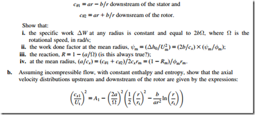
The distributions of the tangential components of absolute velocity with radius are
where a and b are constants. What is the variation of work done with radius? Deduce expressions for the axial velocity distributions before and after the rotor, assuming incompressible flow theory and that the radial gradient of stagnation pressure is zero. At the mean radius, r 5 0.3 m, the stage loading coefficient, ψ 5 ΔW=U2, is 0.3, the reaction ratio is 0.5, and the mean axial velocity is 150 m/s. The rotor speed is 7640 rev/min. Determine the rotor flow inlet and outlet angles at a radius of 0.24 m given that the hub-tip ratio is 0.5.
Assume that at the mean radius the axial velocity remained unchanged (cx1 5 cx2 at r 5 0.3 m). (Note: ΔW is the specific work and Ut the blade tip speed.)
6. An axial-flow turbine stage is to be designed for free-vortex conditions at exit from the nozzle row and for zero swirl at exit from the rotor. The gas entering the stage has a stagnation temperature of 1000 K, the mass flow rate is 32 kg/s, the root and tip diameters are 0.56 m and 0.76 m, respectively, and the rotor speed is 8000 rev/min. At the rotor tip, the stage reaction is 50% and the axial velocity is constant at 183 m/s. The velocity of the gas entering the stage is equal to that leaving. Determine
a. the maximum velocity leaving the nozzles;
b. the maximum absolute Mach number in the stage;
c. the root section reaction;
d. the power output of the stage;
e. the stagnation and static temperatures at stage exit.
Take R 5 0.287 kJ/(kg K) and Cp 5 1.147 kJ/(kg K).
7. The rotor blades of an axial-flow turbine stage are 100 mm long and are designed to receive gas at an incidence of 3o from a nozzle row. A free-vortex whirl distribution is to be maintained between nozzle exit and rotor entry. At rotor exit, the absolute velocity is 150 m/s in the axial direction at all radii. The deviation is 5o for the rotor blades and 0o for the nozzle blades at all radii. At the hub, radius 200 mm, the conditions are as follows:
Assuming that the axial velocity of the gas is constant across the stage, determine
a. the nozzle outlet angle at the tip;
b. the rotor blade inlet angles at hub and tip;
c. the rotor blade outlet angles at hub and tip;
d. the degree of reaction at root and tip.
Why is it essential to have a positive reaction in a turbine stage?
8. The rotor and stator of an isolated stage in an axial-flow turbomachine are to be represented by two actuator discs located at axial positions x 5 0 and x 5 δ, respectively. The hub and tip diameters are constant and the hub-tip radius ratio rh/rt is 0.5. The rotor disc considered on its own has an axial velocity of 100 m/s far upstream and 150 m/s downstream at a constant radius r 5 0.75rt. The stator disc in isolation has an axial velocity of 150 m/s far upstream and 100 m/s far downstream at radius r 5 0.75rt. Calculate and plot the axial velocity variation between 20.5 # x/rt # 0.6 at the given radius for each actuator disc in isolation and for the combined discs when (a) δ 5 0.1rt, (b) δ 5 0.25rt, and (c) δ 5 rt.
9. a. For the fluid element rotating in radial equilibrium about the axis of a turbomachine (Figure 6.2) prove the generalized radial equilibrium equation:
b. At entry to an axial-flow hydraulic turbine, the flow passes through a row of inlet guide vanes giving the water a free-vortex swirl prior to it entering the rotor blade row. The rotor has a root radius of 0.5 m and a tip radius of 1.2 m and the volume flow of water is 45 m3/s. A pressure probe inserted radially into the flow upstream of the rotor to the mean radius indicates a flow angle of 26.1o from the axial direction.
Assuming that the stagnation pressure is constant, determine the static pressure difference between the hub and tip upstream of the rotor as measured on a vertical mercury manometer. Take the density of water as 1000 kg/m3 and the density of mercury as 13:6 3 103 kg=m3.
10. A single-stage axial-flow gas turbine stage with a hub/tip ratio of 0.85 is to be designed to give a free-vortex flow after the rotor row and is required to develop 2.6 MW from a gas flow of 30 kg/s. The gas admitted is at a stagnation temperature and pressure of 1100 K and 430 kPa (abs) and the relevant gas properties are Cp 5 1:15 kJ=kg and γ 5 1:333. At the mean radius the blade speed is to be 250 m/s, the flow coefficient φ 5 0:5, the absolute flow angle α2 5 67o, and the reaction is 0.5. The static pressure at exit is 1.02 kPa.
Sketch an appropriate velocity diagram for the stage and determine
a. the blade loading coefficient, ψ 5 ΔW=U2
b. the flow area and the hub and tip radii
c. the absolute tangential velocity components, cθ2 and cθ3, following the expansion through the nozzle
d. the reaction at the hub and tip.
11. a. An axial-flow fan comprising a stator followed by a rotor is to be made with swirl distributions specified by
c. For the above fan the hub/tip radius ratio is 0.6, the rotational speed is 4010 rpm, the rotor diameter is 1.0 m, the mean reaction is 0.5, the flow coefficient upstream of the rotor at the mean radius φ 5 cx1=Ut 5 0:5, and the stagnation temperature rise is 10oC. Determine
i. the value of A1, and values of cx1=Ut in the range, 0:6 # 0:05 # 1:0 for r=rt and hence find the volume flow rate using the mid-ordinate method;
ii. a value of A2 by repeated iteration of the velocity profile until the correct value of the volume flow is achieved.
Hence, plot the final axial velocity profiles for the upstream and downstream flows.
12. a. A solution of the so-called “direct problem” of the flow in an axial-flow turbomachine can be found using the radial equilibrium equation when the absolute flow angle α is constant and a radial gradient in stagnation enthalpy ðdh0=drÞ 5 ðk=2Þðc2 =rmÞ is present (where k is a constant).
If the variation of α is specified by a 5 2 sin2 α, prove that the velocity variation across the duct is given by
where cm is the velocity at radius r 5 rm.
b. An axial-flow fan with a hub/tip ratio of 0.4, a tip diameter of 1 m is used to compress air at normal temperature and pressure. The rotational speed of the fan is 500 rad/s. The radial gradient of stagnation enthalpy from hub to tip is to be estimated from the following data:
At r=rt 5 0:4, the work coefficient ψh 5 0:6. At r 5 rt, the work coefficient ψt 5 0:25. The entropy is to be assumed constant.
Determine the velocity of the air as a function of radius and plot the results you obtain for
i. k 5 0.6 at α 5 30, 45, and 60o.
ii. k 5 21, 0, 1.0 with α 5 45o.
Comment on the trends caused by the choice of these variables.
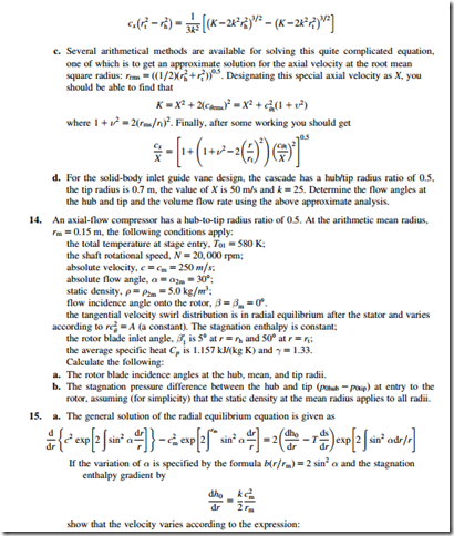
13. a. Inlet guide vanes are to be tested to produce a flow with a tangential velocity distribution cθ 5 k r, where k and K are arbitrary constants. Show that the axial velocity distribution is given by
b. Using the continuity equation derive the following solution for the axial velocity:
 where k is a constant of integration.
b. Using the operational data and sizes given in Problem 12, determine the velocity variation c=cm of an axial fan using the expression given for α 5 30; 45; and 60o and k 5 0.6. Plot your results ðc=cmÞ versus ðr=rtÞ and compare these with the results of problem 6.12. Repeat this calculation for k 5 1.2 and α 5 45o. What conclusion do you draw about the effect made by the increased stagnation enthalpy gradient on the spanwise velocity distribution?


