Components of a Roof Ventilator
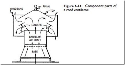
The basic components of a typical roof ventilator are shown in Figure 6-14 and may be listed as follows:
1. Base
2. Barrel
3. Top
4. Windband
5. Airshaft
6. Dampers
The base serves as the connection between the roof and the ven- tilator proper. A trough is usually provided around the inside bot- tom edge of the base to collect any condensation occurring in the ventilator and draw it out to the roof.
As bases are made to fit either a round or square opening and to conform to the shape and slope of the roof, they are essentially tailor-made for each installation.
After leaving the base, the air passes through the barrel (or neck) of the ventilator, which is merely the lower section of the head. It then enters the head proper and is exhausted to the outside air through the openings between louvers. The top, of course, covers the opening in the roof.
The windband is the vertical band encircling the ventilator head. The airshaft is the entire passageway through the ventilator from the roof to the top of the barrel.
The dampers are mechanical devices for closing the airshaft. They assume a number of forms and are referred to according to type as the sliding sleeve, inverted cone, butterfly, and louver.
