Early history of hydraulic turbines
The hydraulic turbine has a long period of development, its oldest and simplest form being the waterwheel, first used in ancient Greece and subsequently adopted throughout medieval Europe for the grinding of grain, etc. A French engineer, Benoit Fourneyron, developed the first commercially successful hydraulic turbine (circa 1830). Later Fourneyron built turbines for industrial purposes that achieved a speed of 2300 rpm, developing about 50 kW at an efficiency of over 80%.
The American engineer James B. Francis designed the first radial-inflow hydraulic turbine that became widely used, gave excellent results, and was highly regarded. In its original form, it was used for heads of between 10 and 100 m. A simplified form of this turbine is shown in Figure 1.1(d). It will be observed that the flow path followed is essentially from a radial direction to an axial direction.
The Pelton wheel turbine, named after its American inventor, Lester A. Pelton, was brought into use in the second half of the nineteenth century. This is an impulse turbine in which water is piped at high pressure to a nozzle where it expands completely to atmospheric pressure. The emerging jet impacts onto the blades (or buckets) of the turbine, which produce the required torque and power out- put. A simplified diagram of a Pelton wheel turbine is shown in Figure 1.1(f). The head of water used originally was between about 90 and 900 m (modern versions operate up to heads of nearly 2000 m).
The increasing need for more power during the early years of the twentieth century also led to the invention of a turbine suitable for small heads of water, i.e., 3-9 m, in river locations where a dam could be built. In 1913, Viktor Kaplan revealed his idea of the propeller (or Kaplan) turbine, see Figure 1.1(e), which acts like a ship’s propeller but in reverse. At a later date, Kaplan improved his turbine by means of swiveling blades, which improved the efficiency of the turbine appropriate to the available flow rate and head.
Flow regimes for maximum efficiency
The efficiency of a hydraulic turbine can be defined as the work developed by the rotor in unit time divided by the difference in hydraulic energy between inlet and outlet of the turbine in unit
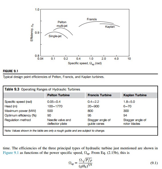
where P is the power delivered by the shaft, ρ is the density of water, HE is the effective head at turbine entry, and Ω is the rotational speed in radians per second. It is remarkable that the efficiency of the multistage Pelton turbine has now reached 92.5% at ΩspD0.2 and that the Francis turbine can achieve an efficiency of 95-96% at an ΩspD1.0-2.0.
The Ωsp regimes of these turbine types are of considerable importance to the designer as they indicate the most suitable choice of machine for an application. In general, low specific speed machines correspond to low-volume flow rates and high heads, whereas high specific speed machines correspond to high volume flow rates and low heads. Table 9.3 summarizes the normal
operating ranges for the specific speed, the effective head, the maximum power, and best efficiency for each type of turbine.
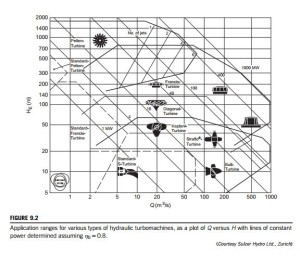
According to the experience of Sulzer Hydro Ltd., of Zurich, the application ranges of the various types of turbines and turbine pumps (including some not mentioned here) are plotted in Figure 9.2 on a ln Q versus ln HE diagram and reflect the present state of the art of hydraulic turbomachinery design. Also in Figure 9.2, lines of constant power output are conveniently shown and have been cal- culated as the product ηρgQHE, where the efficiency η is given the value of 0.8 throughout the chart.
Capacity of large Francis turbines
The size and capacity of some of the recently built Francis turbines is a source of wonder, and they seem so enormous! The size and weight of the runners cause special problems getting them to the site, especially when rivers have to be crossed and the bridges are inadequate.
The largest installation in North America (circa 1998) is at La Grande on James Bay in eastern Canada where 22 units each rated at 333 MW have a total capacity of 7326 MW. A close competitor with the Three Gorges project is the Itaipu hydroelectric plant on the Parana´ river (between Brazil and Paraguay), which has a capacity of 12,600 MW in full operation using 18 Francis turbines each sized at 700 MW.
The efficiency of large Francis turbines has gradually risen over the years and now is about 95%. There seems to be little prospect of much further improvement in efficiency as computable values of losses due to skin friction, tip leakage, and exit kinetic energy from the diffuser are reckoned to account for the remaining 5%. Raabe (1985) has given much attention to the statistics of the world’s biggest turbines. It would appear at the present time that the largest hydroturbines in the world are the three vertical-shaft Francis turbines installed at Grand Coulee III on the Columbia River, Washington, United States. Each of these leviathans has been uprated to 800 MW, with the delivery (or effective) head, HE 5 87 m, Ω 5 85.7 rpm, the runner having a diameter of D 5 9.26 m and weighing 450 ton. Using this data in Eq. (9.1), it is easy to calculate that the power specific speed Ωsp 5 1.74 rad.
Related posts:
Incoming search terms:
- hydrolic turbine
- write historical of hydraulic developmen turbine
- hydrolic mail
- evolution of hydrolic turbine
- historical development of hydraulic turbine
- What is hydraulic turbines history?
- water turbine specific speed
- turbine specific speed chart
- Kaplan turbine / Vertical Kaplan turbine generator unit mail
- hydrolic turbine history
- difference between pelton francis kaplan turbine
- hydraulic turbines history
- hydalic turbine first started
- history of the hydraulic turbine
- historical development of hydrolic turbines
- background of hydraulic turbine


