Installations and Configurations
Just as there are many different soil types and underground applications, utilities have many ways to install underground cable. Some common installation methods include [see NRECA RER Project 90-8 (1993) for more details]:
• Trenching — This is the most common way to install cables, either direct-buried or cables in conduit. After a trench is dug, cable is installed, backfill is added and tamped, and the surface is restored. A trenching machine with different cutting chains is available for use on different soils. Backhoes also help with trenching.
• Plowing — A cable plow blade breaks up and lifts the earth as it feeds a cable into the furrow. Plowing eliminates backfilling and disturbs the surface less than trenching. NRECA reports that plowing is 30 to 50% less expensive than trenching (NRECA RER Project 90-8, 1993). Plowed cables may have lower ampacity because of air pockets between the cable and the loose soil around the cable. Heat cannot transfer as effectively from the cable to the surrounding earth.
• Boring — A number of tunneling technologies are available to drill under roads or even over much longer distances with guided, fluid- assisted drill heads.
Utilities also have a number of installation options, each with tradeoffs:
• Direct buried — Cables are buried directly in the earth. This is the fastest and least expensive installation option. Its major disadvantage is that cable replacement or repair is difficult.
• Conduit — Using conduit allows for quicker replacement or repair.
Rigid PVC conduit is the most common conduit material; steel and HDPE and fiberglass are also used. Cables in conduit have less ampacity than direct-buried cables.
• Direct buried with a spare conduit — Burying a cable with a spare conduit provides provisions for repair or upgrades. Crews can pull another cable through the spare conduit to increase capacity or, if the cable fails, run a replacement cable through the spare conduit and abandon the failed cable. Normally, when the cable is plowed in, the conduit is coilable polyethylene.
• Concrete-encased conduit — Most often used in urban construction, conduit is encased in concrete. Concrete protects the conduit, resist- ing collapse due to shifting earth. The concrete also helps prevent dig-ins.
• Preassembled cable in conduit — Cable with flexible conduit can be purchased on reels, which crews can plow into the ground together.
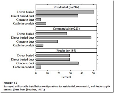
Direct buried Direct buried duct Concrete duct Cable in conduit Direct buried Direct buried duct Concrete duct Cable in conduit Direct buried Direct buried duct Concrete duct Cable in conduit
The flexible conduit is likely to be more difficult to pull cable through, especially if the conduit is not straight. Flexible conduit is also not as strong as rigid conduit; the conduit can collapse due to rocks or other external forces.
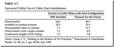
Utilities are split between using direct-buried cable and conduits or ducts for underground residential applications. Conduits are used more for three-phase circuits, for commercial service, and for main feeder applica- tions (see Figure 3.4). Conduit use is rising as shown by a more recent survey in Table 3.7. In a survey of the rural cooperatives with the most underground distribution, Dudas and Rodgers (1999) reported that 80% directly bury cable.
With conduits, customers have less outage time because cables can be replaced or repaired more quickly. In addition, replacement causes much less trouble for customers. Replacement doesn’t disturb driveways, streets, or lawns; crews can concentrate their work at padmounted gear, rather than spread out along entire cable runs; and crews are less likely to tie up traffic. Conduit costs more than direct buried cable initially, typically from 25 to 50% more for PVC conduit (but this ranges widely depending on soil con- ditions and obstacles in or on the ground). Cable in flexible conduit may be slightly less than cable in rigid conduit. While directly buried cable has lower initial costs, lifetime costs can be higher than conduit depending on economic
assumptions and assumptions on how long cables will last or if they will need to be upgraded. Some utilities use a combination approach; most cable is direct buried, but ducts are used for road crossings and other obstacles.
The National Electrical Safety Code requires that direct-buried cable have at least 30 in. (0.75 m) of cover (IEEE C2-1997). Typically, trench depths are at least 36 in.
If communication cables are buried with primary power cables, extra rules apply. For direct-buried cable with an insulating jacket, the NESC requires that the neutral must have at least one half of the conductivity of the phase conductor (IEEE C2-1997) (it must be a one-half neutral or a full neutral).
Some urban applications are constrained by small ducts: 3, 3.5, or 4-in. diameters. These ducts were designed to hold three-conductor paper-insu- lated lead-sheathed cables which have conductors squashed in a sector shape for a more compact arrangement. Insulation cannot be extruded over these shapes, so obtaining an equivalent replacement cable with extruded insula- tion is difficult. Manufacturers offer thinner cables to meet these applications. For triplex cable, the equivalent outside diameter is 2.155 times the diameter of an individual cable. So, to fit in a 3-in. duct, an individual cable must be less than 1.16 in. in diameter to leave a 1/2-in. space (see Table 3.8 for other duct sizes). Some cable offered as “thin-wall” cable has slightly reduced insulation. For 15-kV cable, the smallest insulation thicknesses range between 150 and 165 mil as compared to the standard 175 mil (EPRI 1001734, 2002) (the ICEA allows 100% 15-kV cable insulation to range from 165 to 205
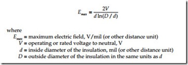
mil (ANSI/ICEA S-97-682-2000, 2000)). One manufacturer has proposed reduced insulation thicknesses based on the fact that larger conductors have lower peak voltage stress on the insulation than smaller conductors (Cinque- mani et al., 1997), for example, 110-mil insulation at 15 kV for 4/0 through 750 kcmil. The maximum electric field (EPRI 1001734, 2002) is given by
So, a 750-kcmil cable with 140-mil insulation has about the same maximum voltage stress as a 1/0 cable with 175-mil insulation at the same voltage. Nevertheless, most manufacturers are reluctant to trim the primary insula- tion too much, fearing premature failure due to water treeing. In addition to slightly reduced insulation, thin-wall cables are normally compressed copper and have thinner jackets and thinner semiconducting shields around the conductor and insulation. EPRI has also investigated other polymers for use in thin-wall cables (EPRI TR-111888, 2000). Their investigations found promising results with novel polymer blends that could achieve insulation strengths that are 30 to 40% higher than XLPE. These tests suggest promise, but more work must be done to improve the extrusion of these materials.


