Transformer Testing
Transformers may be tested with AC or DC voltage. Overall, AC voltage is preferable to DC voltage for testing transformers because AC voltage simu- lates the internal stress that the transformers experience during operating conditions.
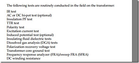
The following tests are routinely conducted in the field on the transformer:
The IR and DC hi-pot tests are discussed in Chapter 2; the PF and excitation tests are discussed in Chapter 3; the transformer insulating fluid and dis- solved gas tests are discussed in Chapter 4; and the remaining tests listed above are discussed next.
5.8.1 AC Hi-Pot Test
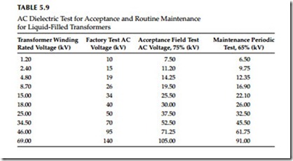
The AC hi-pot test is applied to evaluate the condition of transformer wind- ings. This test is recommended for all voltages, especially those above 34.5 kV. For routine maintenance testing of transformers, the test voltage should not exceed 65% of factory test voltage. However, the hi-pot test for routine maintenance is generally not employed on transformers because of the possibility of damage to the winding insulation. This test is commonly used for acceptance testing or after repair testing of transformers. The AC HV test value should not exceed 75% of the factory test value. When AC hi-pot testing is to be used for routine maintenance, the transformer can be tested at rated voltage for 3 min instead of testing at 65% of factory test voltage. The AC hi-pot test values for voltage systems up to 69 kV are shown in Table 5.9. Testing procedures and test connections are similar to the DC hi-pot tests described in Chapter 2.
TTR Test
The TTR test applies voltage to one winding of a transformer and detects the voltage being generated on another winding on the same core.
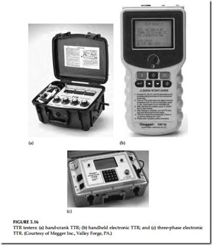
In the case of a low voltage hand-crank powered TTR, 8 V AC is applied to the low-voltage winding of the transformer under test and a reference transformer in the TTR set. The HV windings of the transformer under test and the TTR reference transformer are connected through a null detecting instrument. After polarity has been established at 8 V, when the null reading is zero, the dial readings indicate the ratio of the transformer under test.
In the case of an electronic TTR test set, a voltage (typically 80 V AC) is applied to the HV winding of the transformer under test. The voltage generated on the low-voltage winding is measured and the voltage ratio between high and low windings is calculated. Voltage ratio is proportionally equal to turns ratio. The hand-crank powered TTR, the handheld electronic TTR, and the three-phase electronic TTR are shown in Figure 5.16a through c, respectively.
The TTR test provides the following information:
• It determines the turns ratio and polarity of single- and three-phase transformers, one phase at a time.
• It confirms nameplate ratio, polarity, and vectors.
• It determines the ratio and polarity (but not voltage rating) of transformers without markings. Tests include all no-load tap positions on a transformer. Tests include all load taps on load, tap changer (LTC) transformers if connected for voltage ratio control. On LTC trans- formers connected for phase angle control, ratio and polarity are per- formed in neutral positions only. If tested on load taps, readings may be taken for reference for future comparison, but will deviate from nameplate ratings. LTC taps may be confirmed by application of low three-phase voltage and reading volts and the phase angle for each.
• Identify trouble in transformer windings, such as open-circuit and short-circuits of turn-to-turn sensitivity. The standard deviation as defined by ANSI/IEEE C57.12.00-2006, Section 9.1 states that results should be within 0.5% of nameplate markings, with rated voltage applied to one winding. The TTR with accuracy of 0.1% is accepted as a referee.
The following procedures are used for conducting the TTR test:
Transformer is isolated and tagged and leads disconnected Read transformer nameplate Observe the polarities and vectors (phasors) Calculate ratios for each no-load and load tap position Set up data test form as follows:
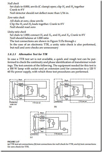
Make the null check, zero ratio check, and unity ratio check on the hand-crank TTR.
Null check
Set dials to 0.000, anvils (C clamp) open; clip H1 and H2 together Crank to 8 V Null detector should not deflect more than 1/16 in.
Zero ratio check
All dials at zero, close anvils Clip the H1 and H2 leads together. Crank to 8 V Null should read zero
Unity ratio check
Set dials to 1.000; connect H1 and X1, and H2 and X2, Crank to 8 V Null should balance at 1.000 ratio The test connections are shown in Figure 5.17a through c In the case of an electronic TTR, a unity ratio check is also performed, but null and zero checks are unnecessary
Alternative Test for TTR
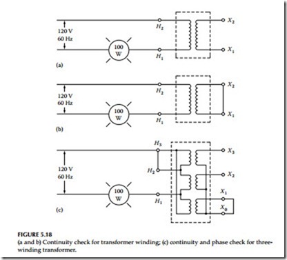
In case a TTR test set is not available, a quick and rough test can be per- formed to check the continuity and phase identification of transformer wind- ings. The test consists of the following. The equipment needed for this test is a 100 W lamp with socket and an extension cord for connection to a 120 V 60 Hz power supply, with which three test procedures are performed.
Test 1: Connect the 120 V, 60 Hz power through the lamp to the trans- former primary, terminals as shown in Figure 5.18a. Leave the transformer secondary winding open. The lamp will burn dimly.
Test 2: Maintain connections as described in test 1, but now short the secondary winding. The lamp should burn with great brilliance. If the lamp still burns with somewhat less than full brilliance, inves- tigate for problems in the transformer winding. Connections for this test are shown in Figure 5.18b.
Test 3: This test is similar to tests 1 and 2, but as applied to a three- phase transformer for phase identification and phase continuity check. Conduct tests 1 and 2 for each winding of a three-phase trans- former individually with the remaining windings left open. The test connections are shown in Figure 5.18c.
TTR Capacitor
The TTR test may be performed at higher voltages using a capacitor in combination with the PF test set. With the addition of the TTR capacitor,
the Doble’s PF test set M4100 (discussed in Chapter 3) can measure the turns ratio of power transformers at potentials up to 10 kV. Using the capacitor in place of the standard TTR test set, allows a higher test voltage, up to 10 kV, to be applied to the primary winding. Most TTR test sets are limited to less than 100 V which greatly reduces the voltage on the secondary windings. The benefits of the HV TTR tests are that it identifies problems and anomalies in the electric and magnetic circuit (i.e., core and coils) of the transformer that are not revealed with the low-voltage TTR tests.
Polarity Test
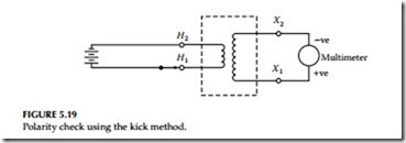
The polarity test can be performed with the TTR on power, distribution, and potential transformers. However, for current transformers the TTR test is not used. Instead a test commonly known as the kick test, consisting of applying a DC battery and multimeter is used. The kick test can also be used for power distribution, and potential transformers; however, the TTR test is preferred. The connections for a kick test for a current transformer are shown in Figure
5.19. The DC battery voltage is usually about 7.5 V, and the multimeter volt- age range is set for 3 V full-scale. The negative terminal of the battery is connected to current transformer terminal H2 and the positive side is left hanging for the time being. The multimeter positive terminal is connected to the trans- former secondary terminal X1 and negative terminal to X2. To conduct the test, touch the positive side battery jumper to transformer terminal H1 and notice the multimeter scale indication, if the multimeter scale kick is up scale, the transformer is connected in subtractive polarity. If the kick is down scale, it is connected in additive polarity.
Induced Potential Test
The induced potential test is a proof test and performed at higher voltage levels than normal operating voltages. Under this test, turn-to-turn insulation and phase-to-phase insulation are stressed at 65% of factory test voltage at higher frequency than 60 Hz, such as 200–300 Hz. The frequency of conduct- ing this test should be 5 years or more for large transformers.
The induced potential test for transformers which receive the full standard applied potential test is made by applying between the terminals of one
winding a voltage of twice the normal voltage developed in the windings. It is applied for 7200 cycles, and the duration should not exceed 60 s.
As the induced potential test overexcites the transformer, the frequency of the applied potential should be high enough to prevent the exciting current of the transformer under test from exceeding about 30% of its rated load current. Ordinarily this requirement necessitates the use of a frequency of 120 Hz or more, when testing 60 Hz units.
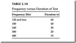
When frequencies higher than 120 Hz are used, the severity of the test is abnormally increased and for this reason the duration of the test should be reduced as shown in Table 5.10.
The voltage should be started at one-quarter or less of the full value and be brought up gradually to full value in not more than 15 s. After being held for the time specified in Table 5.10, it should be reduced slowly (in not more than 5 s) to one-quarter of the maximum value or less, and the circuit opened.
When transformers have one winding grounded for operation on a grounded-neutral system, special care should be taken to avoid high electro- static stresses between the other windings and ground.
In the case of transformers having one end of the HV winding grounded during the induced potential test, the ground on each winding may be made at a selected point of the winding itself or of the winding of a step-up transformer which is used to supply the voltage or which is merely connected for the purpose of furnishing the ground.
Three-phase transformers may be tested with single-phase voltage. The specified test voltage is induced, successively, from each line terminal to ground and to adjacent line terminals. The neutrals of the windings may or may not be held at ground potential during these tests.
When the induced test on the winding results in a voltage between termi- nals of other windings in excess of the low-frequency test voltage specified, the other windings may be sectionalized and grounded. Additional induced tests should then be made to give the required test voltage between terminals of windings that were sectionalized.
FRA
The FRA test may be performed as an impulse response or as a SFRA test. The impulse method estimates the frequency response whereas sweep frequency response method measures the response over a range of frequencies of interest. Both the FRA and SFRA methods are nondestructive tests used to detect if deformation (displacement) of core and coils has taken place. Sweep frequency response is a major advance in transformer condition analysis, allowing visualization of the inside of the transformer’s tank without costly detanking. The standard definition of FRA is the ratio of a steady sinusoidal output from a test object subjected to a steady sinusoidal input. SFRA is a proven technique for making accurate and repeatable measurements. There is a direct relationship between the geometric configuration of the winding and core, and the series and parallel impedance network of inductance, capacitance, and resistance. This network can be identified by its frequency-dependent transfer function.
FRA testing by the sweep frequency response method uses network analysis tools to determine the transfer function. Changes in the geometric configuration alter the impedance network, and in turn alter the transfer function. This enables a wide range of failure modes to be identified. Analysis of SFRA test results relies, in part, on comparison between phases and against previous test results. Commonality between transformers of the same design is also expected. The SFRA tests are actually a series of many tests over a band of frequencies from 20 Hz to 2 MHz. The SFRA test results can be referred to as traces that are shown on a graph. The x-axis of the graphs is the test frequency and the y-axis is the magnitude in decibels (db). These traces show the ratio of the output voltage to the input voltage of the transformer circuit under test at each of the frequencies. It has been shown that these traces are a signature that is related to the distributed resistance, inductance, and capacitance (RLC) of the components within the transformer. They should follow certain general shapes and favorable comparisons should exist among the phases of a transformer, with previous test results, and among transformers of identical design. The first, or benchmark, traces also provide a valuable tool to identify winding movement in the future.
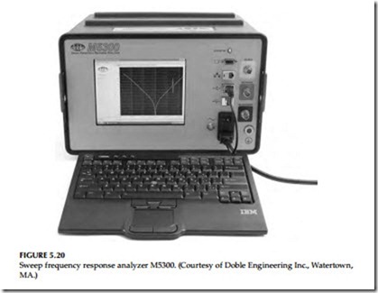
As compared to the “impulse” technique, SFRA is preferred for frequency domain measurements. It covers the full dynamic range and maintains the same energy level for each frequency, providing accurate, consistent results. A high signal-to-noise ratio across the entire 20 Hz to 2 MHz frequency range ensures valid measurements. Sweep frequency response analyzers (Figure 5.20) detect mechanical failure or movement of windings due to short circuits, mechan- ical stresses, or transportation. These tests are used to ensure transformer performance, reduce maintenance cost, and increase service life. System faults, short circuits, aging, or even handling during transportation can compromise a transformer’s mechanical structure. Since these problems are difficult to detect, they usually go unnoticed and worsen over time, leading to loss of per- formance and possibly failure. Until recently, the options for dealing with these critical problems were limited. If such damage was suspected in a transformer, the options were limited. These problems could be ignored and hope for the best, or detank the transformer to make a costly and time-consuming visual inspection. Even that might not reveal the damage.
The sweep frequency response analyzer adds a powerful tool to the quality control and maintenance toolkit, allowing a look inside the transformer to detect even subtle changes in the mechanical structure of the core and windings—without costly detanking. This is the most effective diagnostic tool for detecting mechanical problems in power transformers. The instru- ment sends an excitation signal into the transformer and measures the returning signals. Comparing this response to baseline and other results (such as from similar units) allows identification of deviations. Typical internal mechanical problems identified in transformers with FRA are:
• Core movement
• Winding deformation and displacement
• Faulty core grounds
• Partial winding collapse
• Hoop buckling
• Broken or loosened clamping structures
• Shorted turns and open windings
These test methods are generally used on large HV power transformers because they are sensitive tests to detect winding distortion and deformation (i.e., in coils, layers, turns, and leads) in power transformers. A significant
amount of deformation can occur in the windings as a result of high through fault currents which can go undetected before an actual failure occurs. The voltage stress changes in the winding insulation structure after the onset of initial winding deformation. Over time the winding deformation will lead to partial discharges and gassing. However, by the time partial discharge and subsequent gassing appear degradation of the transformer has already occurred. Winding deformation is one of the first and fundamental precur- sors to indicate a degraded condition in the transformer windings. The FRA tests are performed at the factory and also in the field on transformers off- line. The results are compared to determine if changes have occurred in the transformer. Specialized test equipment is required to perform FRA or SFRA tests. In general, the procedure requires the transformer to be de-energized and isolated. Each individual phase of every winding is tested. One set of tests is done by injecting the signal at one end of the winding and measuring the other end. Another test is done by injecting the signal at one end of a primary winding and measuring the corresponding secondary winding.
DC Winding Resistance
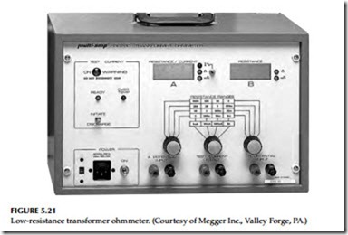
This test measures the DC resistance of the transformer leads and windings and is made with a low-resistance ohmmeter or a Kelvin bridge. Winding resis- tance will change due to shorted turns, loose connections, or deteriorating con- tacts in tap changers. One of the problems associated with measuring the DC resistance of a transformer is the inductive circuit that must be energized. The inductance must be charged and stabilized in order to allow an accurate read- ing to be made. Special low-resistance ohmmeters are available specifically for the purpose of performing this test. A low-resistance ohmmeter specifically made for measuring transformers winding resistance is shown in Figure 5.21.
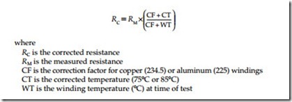
The test procedure for measuring DC winding resistance requires the trans- former to be de-energized and isolated. Both the primary and secondary ter- minals should be isolated from external connections, and measurements made on each phase of all windings. The measured resistance should be corrected to a common temperature such as 75°C or 85°C using the following formula:
Measurements should be made on all tap changer positions (if present) and compared to previous or factory test values. The test values after temperature correction should be compared with the factory test values or previous years’ test results for evaluating the condition of the transformer windings and leads. The acceptance criteria for the field-measured values after temperature correction should be within 2% of the factory values. A change greater than the acceptance criteria is indicative of short-circuited turns, poor joints, or bad tap changer contacts. This test should be performed during acceptance testing and when other maintenance electrical tests are conducted.
Transformer Core Ground Test
An IR measurement is made to determine the presence of unintentional core grounds. In general, the laminated cores of power transformers are insu- lated from ground, and intentionally grounded at a single point. Typically this grounding point can be accessed at the top of the transformer, either externally at a small bushing or internally behind a manhole cover.
Unintentional core grounds can develop due to shipping damage, though faults, or deterioration of core insulation. Any of these factors can cause excessive localized heating through circulating currents in the core and surrounding structure, leading to the generation of specific gases in the insulating oil.
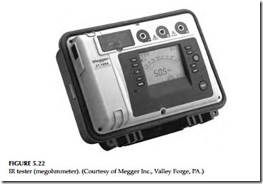
The procedure for the test requires the transformer to be de-energized and isolated. The intentional core ground connection is lifted and the DC IR test is made between the core connection and the grounded transformer enclosure. Acceptable readings are 100 MΩ or greater. An IR tester (megohmmeter or Megger) for performing this test is shown in Figure 5.22.
Polarization Recovery Voltage Test
The transformer insulation systems are composites of two insulating materials: cellulose fiber (paper) and insulating oil. This structure shows
space-charge polarization effects which are strongly influenced by the moisture content and aging products. These cause a reduction of the time constant. The time constant caused by space-charge polarization exceeds 10 ms and, in the case of new dry insulation, even 1000 s.
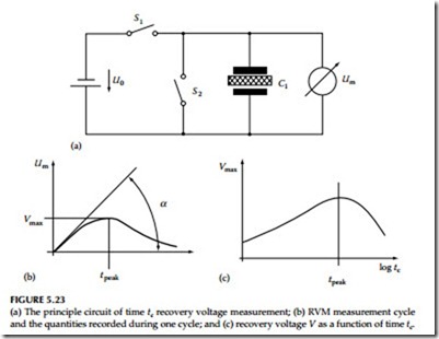
Figure 5.23a shows the circuit of a recovery voltage meter (RVM). Switch S1 is closed for a time tc and DC voltage source U, applies a certain charge to the capacitor (test object), Switch S1 then opens and switch S2 closes for a time td (normally td = tc/2). Part of the capacitor charge is dissipated, then switch S2 also opens and the residual capacitor charge produces a voltage at the capacitor electrodes (Figure 5.23b).
Two typical parameters of this so-called recovery voltage are its maximum value (Vmax) and initial slope (tan d). If the time tc is systematically increased, together with time td from a small initial value, a different value of Vmax and initial slope tan d will be obtained for each time tc.
Figure 5.23c shows the variation of Vmax with tc; it is easily proved that the Vmax/tc curve peaks at the time constant value, i.e., tcritcal = T. This result shows that the Vmax/tc curve also represents a polarization spectrum with maximum value at the insulation time constants.
The Measuring Instrument
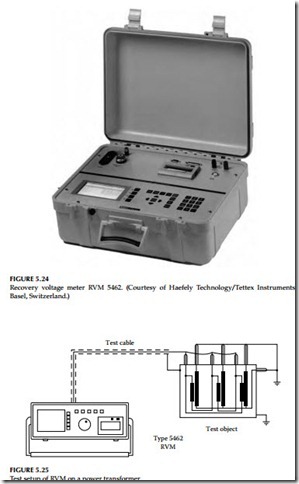
The Tettex RVM 5462 (Figure 5.24) was developed for automatic execution of the series of measurements required for determination of the polarization spectra. It is a portable microprocessor-controlled automatic system suitable for field use. Measurement results are displayed in digital or diagrammatical form. Operation and adjustment of the instrument is through a menu-driven program, with provision for fully automatic measurement sequences or single manual measurements where required. The instrument has an LCD screen display and an alphanumerical printer for test data results.
Standard options include an RS232C interface and screened two-core HV cable for connection to the test object. Analysis software interprets the data and produces definitive moisture content as a percentage (%) of paper mass and a qualitative interpretation of polarization spectrum.
The standard settings in the automatic measurement program ensure effective acquisition of the significant part of the polarization spectrum for power transformer oil/paper insulation.
In automatic measurement mode the instrument displays:
• Recovery voltage peaks and initial slopes with, corresponding charge time tc
• All measured parameters (Umax, tan d, tc, etc.), the characteristic values (tc/td) will be memorized, displayed, and/or printed out Test Setup for Recovery Voltage Measurement on Power Transformers
As shown in Figure 5.25, the terminals of the transformer must be disconnected from the system. The ends of the low-voltage windings must all be joined and connected to the HV core of the instrument test lead. The ends of all other windings must be joined together and connected to the tank ground and the low-voltage core of the test lead. The instrument has the capability of charging voltage at 2000 V DC, tc/td = 2, and tc time range of 10 ms to 10,000 s.
Evaluation of Measured Polarization Spectra
The electrical properties and reliability of the oil/paper insulation used on most power transformers depend very heavily on the state (aging and mois- ture content) of the oil and, even more so, on that of the paper. Oil state is fairly easily assessed by conventional oil sample analysis methods such as Karl-Fischer moisture measurement, PF, etc., but these provide very little information on the state of the paper insulation.
As will be seen from the following examples, the state of oil-impregnated paper can be ascertained directly from the polarization spectrum without any need to take and analyze an oil sample.
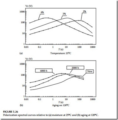
Figure 5.26 shows spectra measured at constant temperature on oil- impregnated paper insulation laboratory models.
The curves in Figure 5.26a show spectra recorded at varying moisture content on the insulation model. Figure 5.26b shows similar curves obtained under artificial aging of varying duration.
These curves clearly show that the behavior of the spectrum (especially displacement of the curve peak toward small time constants) closely reflects changes of state, i.e., degradation of the dielectric, i.e., oil/paper insulation.
