The direct current (DC) motor
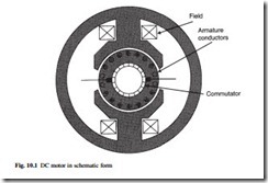
History will recognize the vital role played by dc motors in the development of industrial power transmission systems, the dc machine being the first practical device to convert electrical power into mechanical power. Inherently straightforward operating characteristics, flexible performance and high efficiency have encouraged the wide- spread use of dc motors in many types of industrial drive applications. The basic construction of a dc motor is shown in Fig. 10.1.
Standard dc motors are readily available in one of two main forms:
● wound-field, where the magnetic flux in the motor is controlled by the current flowing in a field or excitation winding, usually located on the stator
● permanent magnet, where the magnetic flux in the motor is created by permanent magnets which have a curved face to create a constant air-gap to the conventional armature, located on the rotor. These are commonly used at powers up to approximately 3 kW.
Torque in a dc motor is produced by the product of the magnetic field created by the field winding or magnets and the current flowing in the armature winding. The action of a mechanical commutator switches the armature current from one winding to another to maintain the relative position of the current to the field, thereby producing torque independent of rotor position.
The circuit of a shunt-wound dc motor (Fig. 10.2) shows the armature M, the armature resistance Ra and the field winding. The armature supply voltage Va is supplied typically from a controlled thyristor system and the field voltage Vf from a separate bridge rectifier.
As the armature rotates, an electromotive force (emf ) Ea is induced in the armature circuit and is called the back-emf since it opposes the applied voltage Va (according to Lenz’s Law, see section 2.2.4). The Ea is related to armature speed and main field flux by
where n is the speed of rotation, φ is the field flux and k1 is a motor constant. From Fig. 10.1 it is seen that the terminal armature voltage Va is given by
(or total power supplied = power output + armature losses). The interaction of the field flux and armature flux produces an armature torque as given in eqn 10.4.
where k2 is a motor constant and If is the field current. This confirms the straight- forward and linear characteristic of the dc motor and consideration of these simple equations will show its controllability and inherent stability. The speed characteristic of a motor is generally represented by curves of speed against input current or torque and its shape can be derived from eqns 10.1 and 10.2:
If the flux is held constant by holding the field current constant in a properly compen- sated motor then
From eqns 10.4 and 10.6, it follows that full control of the dc motor can be achieved through control of the field current and the armature current. In the dc shunt wound motor shown in Fig. 10.2, these currents can be controlled independently. Most industrial dc motor controllers or drives are voltage fed; that is to say that a voltage is applied, and the current is controlled by measuring the current and adjusting the voltage to give the desired current. This basic arrangement is shown in Fig. 10.3.
DC motors exist in other formats. The series dc motor shown in Fig. 10.4 has the field and armature windings connected in series. In this case the field current and
armature current are equal and show characteristically different performance results, though still defined by eqns 10.4 and 10.6.
In the shunt motor the field flux φ is only slightly affected by armature current, and the value of IaRa at full load rarely exceeds 5 per cent of Va, giving a torque–speed curve shown typically as a in Fig. 10.6, where speed remains sensibly constant over a wide range of load torque.
The compound-wound dc motor shown in Fig 10.5 combines both shunt and series characteristics.
The shape of the torque–speed characteristic is determined by the resistance values of the shunt and series fields. The slightly drooping characteristic (curve b in Fig. 10.6) has the advantage in many applications of reducing the mechanical effects of shock loading.
The series dc motor curve (c in Fig. 10.6) shows that the initial flux increases in proportion to current, falling away due to magnetic saturation. In addition the armature circuit includes the resistance of the field winding and the speed becomes roughly inversely proportional to the current. If the load falls to a low value the speed increases dramatically, which may be hazardous, so, the series motor should not normally be
used where there is a possibility of load loss. But because it produces high values of torque at low speed and its characteristic is falling speed with load increase, it is useful in applications such as traction and hoisting, and some mixing duties where initial stiction is dominant.
Under semiconductor converter control with speed feedback from a tachogenerator, the shape of the speed–load curve is largely determined within the controller. It has become standard to use a shunt dc motor with converter control even though the speed–load curve, when under open-loop control is often slightly drooping.
The power-speed limit for the dc motor is approximately 3 × 10⁶ kW rev/min, due to restrictions imposed by the commutator.


