Percolation and Network Resiliency
The dynamic evolution encountered in a fully connected network, where any node is connected to every other nodes within the network, by removing components from the system, either in a random fashion or following some logic, is called network percolation [5]. The percolation process is divided into two subgroups, depending on the type of component being removed. In case of the power system, most cascades initiates from malfunctioning of transmission lines or links, but sometimes it is not edges in the network that fail but the vertices, i.e., substations or bus bars in the grid. In order to distinguish these two types of failure involved in the percolation phenomena, we could outline them as edge percolation on one hand and vertex percolation on the other. Historically, in fact, these processes are called bond percolation and site percolation. This nomenclature has been derived from research, in the field of physics and mathematics, on percolation process. In this chapter, we will consider a percolation process, which involves both edge and node removal, consistent with transmission lines tripping and out-of-service substations due to low-voltage or other reasons.
There is more than one way in which vertex or edge removal can be modeled in a power grid. In the simplest form, the components could be removed in a random fashion. We could, for example, take away some specified fraction of the vertices chosen uniformly at random from the entire power grid. This is the most commonly studied form of percolation. There, of course, are many feasible alternatives. One commonly used alternative removal scheme consists of removing vertices or edges according to a centrality measure, e.g., degree centrality or betweenness centrality. For example, components can be removed in order of betweenness from the highest to the lowest. The targeted removal of vertices according to their degree proved to be an effective vaccination strategy for the control of diseases.
By tradition, the probability involved with parameterizing the percolation process is called the occupation probability, /, which is a probability that a bus or line is functional or present in the power grid. Thus, if the power grid is fully functional with all the components operating then the occupational probability
/ ¼ 1, no elements are nonfunctional or have been removed, and / ¼ 0 is an indication that no elements are occupied which may happen when there is a large blackout totally containing the entire grid.
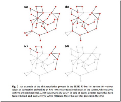
An example of site percolation process is demonstrated in Fig. 2 for IEEE 30 bus test system with 30 nodes and 43 edges. In Fig. 2a, all vertices are present or occupied, they are connected together via transmission lines or edges into a single connected component. Now, if we concentrate on other panels in the same figure, a snapshot of the percolation process is observed. In Fig. 2b, 24 out of 30 vertices are functional, represented by grey color nodes, giving an occupation probability of / ¼ 0:80. Six nonfunctional nodes knocks down 12 adjacent edges, the removed transmission lines are represented by light grey-colored edges. The remaining vertices still compose a single connected component through the intact edges. Figure 2c shows a situation during the percolation process, where more vertices along with associated edges have been removed, and the remaining vertices are no longer connected together. The vertices are split into two small components. In Fig. 2d, all vertices have been removed and the network collapses.
The process that is demonstrated in this small example is a typical percolation behavior. When / is large, close to unity, the vertices tend to be connected together forming a giant connected component spanning most the grid. As the occupation probability decreases, for some reason or the other, the cohesiveness of
the grid decreases, and the grid can no longer function as a single entity and collapses into various small components. The process can be understood in a reverse fashion, when the occupation probability, / is low many small components exist in the network, and with the increase in the occupation probability small components are merged together to form a single large connected component, occupying the whole network.
Evolution of the power grid can be thought of as the building dynamics of the connected components in the network. In the early days of the electricity genera- tion, generators supplied local areas only building a locally distributed small- connected components spanning various regions of a continent. As the technology flourished, with the invent of transformer, long distance power transmission was made possible. The grid began to form expand in size and number of components and finally giving rise to a massive machine running in unison with hundreds of thousands of components connected altogether.
Interconnection has many benefits such as fewer generation capacity required as a reserve for peak load and spinning reserve, economical and reliable energy generation and transmission to name a few. But the advantages come with a great adversity of large-scale blackouts, where small initial failure in amplified and
large-scale cascades are propagated through the system. This process of cascading can be compared with the percolation phenomenon. Generally, the power grid runs as a single component with every substations and transmission lines fully functional, resembling the percolation process sub case as shown in Fig. 2a and / ¼ 1. Failure of a single transmission line or substation produces stress on the system because the load of the failed component is shifted upon the occupied ones. During a much stressed condition, the system operating in a heavily loaded condition, the shift of load may exceed the safe operating limit of some components and those may fail consequently, exerting even more stress on the grid. This chain of event continues and the grid in broken down with small connected components serving only local loads, similar to the percolation phenomenon with the occupation probability, 0\/\1. In an extremely bad condition, the process of cascading proceeds even further giving birth to entire system collapse, as in the percolation process with / ¼ 0.
The creation and demise of the giant component during the percolation process is known as a percolation transition. The point at which the percolation transition occurs is called the percolation threshold. The threshold value of the occupation probability suggests different aspects of grid robustness and vulnerability. Larger values of / in the percolation threshold indicate the system is more vulnerable than the system with lower critical occupational probability, /cr . Removal of very
few nodes breaks the cohesiveness of the grid and makes the system nonfunctional, where /cr is very high. Lots of components, within the grid, have to run properly in order to maintain the functionality of this type of system. On the other hand, systems with low critical occupational probability show a great degree of robustness. In order to reduce the functionality of these types of networks, lots of components have to be taken out, making the system less vulnerable to random attacks.
In percolation studies the term ‘‘component’’ is used to indicate the connected portion of the unaffected network, whereas ‘‘cluster’’ refers to the components that exist in the network after and during the breakdown process. In this chapter, we will use the term ‘‘component’’ to refer to connected group of vertices (substations, bus bars, generators, and loads) on the original network before any vertices or edges have been removed and ‘‘cluster’’ to refer to those after removal.
Delivery of electricity to the consumer end is the function of the overall power grid. Power companies and consumers are mainly concerned about providing sufficient power to the consumers, not the connectivity of the grid after failure. As it turns out, the nature in which the power grid is evolved gives the power grid sufficient robustness to deliver local power even if there is a cascade going on within the system. The total capacity of the connected generators within the dis- connected area must be greater than the local load demand in order to maintain the balance of consumed and generated power.
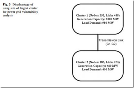
Figure 3 illustrates the situation in case of a two cluster power grid. Both cluster 1 (C1) and cluster 2 (C2) are capable of maintaining the local load demands, but the use of a simple topological measure gives a different picture. C1 contains 252 nodes and 458 links, whereas the second cluster C2 has 183 vertices and 253 links.
The load and generation capacity of the two clusters are 950, 1,000 MW, and 400, 480 MW, respectively. Removal of C1–C2 transmission link makes the size of the largest component to shrink to 0.57, almost 40 % loss of the system functionality, but both of the clusters have ample reserve to supply local demand. Hence, size of largest cluster may not be a good indication of topological vulnerability [16].
Researchers have proposed many alternative definitions of network robustness which are described below:
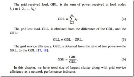
The grid received load, GRL, is the sum of power received at load nodes


