Thermal Impedance Model with Chip Number Information
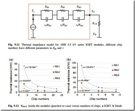
According to the datasheets of IGBT modules, the thermal impedance is modeled as three layers Foster RC network inside the modules (from junction to case ZthJ−C), and a thermal resistance outside the modules (from case to heat sink RthC−H), as
indicated in Fig. 9.11. The thermal impedance model with chip number information can be acquired by fitting function of the thermal parameters provided by datasheets of various current ratings of IGBT modules.
The thermal resistances Rth1, Rth2, and Rth3 in Fig. 9.11 of various ratings of IGBT modules with relation to the calculated chip numbers can be plotted in Fig. 9.12 [16], where the fitting function is also indicated. It can be seen that the thermal resistances Rth1 − Rth3 of both IGBT and diode inside the IGBT modules are inverse proportional to the chip number N, which is consistent with the thermal resistance physical model [15]:
where N is the number of chips, A is the physical area pr. chip, d is the thickness of material, λ is the thermal conductivity constant (W/m*K), and MRth is a fitting parameter.
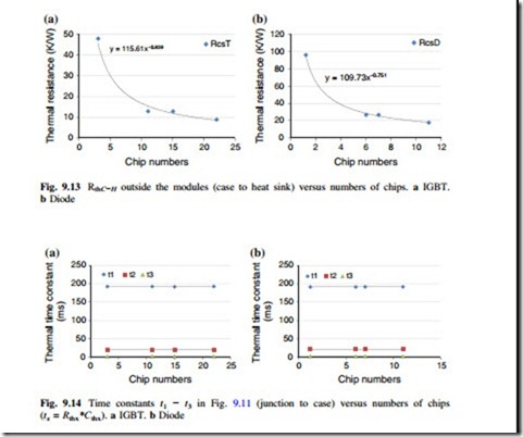
In respect to the thermal resistance from case to heat sink RthC−H (outside the module), it is more related to the base plate size of module case as well as pack- aging technology; therefore, RthC−H is no longer inverse proportional to the chip numbers N, as plotted and fitted in Fig. 9.13.
The time constant of the thermal impedance in Fig. 9.11 (τ1 − τ3) with relation to the chip numbers of IGBT modules is plotted in Fig. 9.14. It can be seen that the time constants of the thermal impedance inside the IGBT modules are kept constant with different chip numbers, and this characteristic is consistent with the time constant physical model, which is represented as [15]
 The c is the factor proportional to heat in (Ws/g*K), and ρ is the density of materials (g/cm3). In the time constant function (9.9), it can be seen that there is no item for the chip numbers N, which means that the time constant of thermal impedance is only related to the thickness of the chips, which should not be deviated in various current ratings of IGBT modules.
In summary, the thermal impedance model with the chip number information for both IGBT and diode of IGBT modules can be written as


