Power electronic circuits and devices
Introduction
The use of solid-state techniques for the control and conversion of electrical power is now commonplace, with applications ranging from small dc power supplies for electronic devices, through actuator and motor drive systems, to large active filters and static power compensators for power transmission and distribution systems.
The aim here is to review the main classes of circuits and devices that are currently used, emphasizing the basic operating principles and characteristics. The opening sections cover the traditional diode-based ac–dc converters, starting with the three- pulse circuit and leading to the twelve-pulse configuration, and including the supply current characteristics. Thyristor phase control techniques are also briefly described. The following sections introduce the principal active devices that are in common use, namely the MOSFET and the IGBT (insulated gate bipolar transistor), then, starting with simple dc–dc converter switching cells, switching and inverter circuits are explained, leading to sinusoidal PWM methods. Finally, there is a short review of high-frequency power supplies.
Diode converters
Three-pulse rectifier
The three-pulse rectifier in Fig. 11.1 supplies a resistive load in series with a filter inductor, the inductor being large enough to ensure that the load current is continuous and ripple-free. The circuit is a half-wave rectifier, with each supply line, A, B and C, being connected through a single diode to the top of the load, the neutral wire forming the return path. The circuit waveforms follow directly from the assumption of a continuous and smooth load current:
● One of the three diodes must always be in conduction to provide a path for the load current.
● Only one diode may conduct at once, since otherwise two of the supply lines would have the same voltage, and this only occurs momentarily as the voltages cross each other.
● The diode that conducts at any instant is determined by the supply line with the largest positive voltage, since this voltage will forward bias the diode in that line and reverse bias the other two diodes.
Therefore the diodes conduct in sequence for 2p/3 radians or 120°, and the rectifier output voltage vD is the maximum value of the three line-to-neutral voltages. Since the vD waveform repeats every 2p/3 radians, or three times each utility cycle, it is known as a three-pulse rectifier, and the output voltage ripple frequency is three times the supply frequency.
As the repetition period of vD is 2p/3 radians, the average value of the waveform may be calculated by integrating over this interval:
where VLL is the amplitude or peak value of the line-to-line supply voltage.
Since the circuit only draws a unidirectional current from each supply line, and also uses the neutral wire for the return current, it is rarely used in practice, but it is simple to understand, and is helpful in analyzing more complex circuits.
Six-pulse rectifier
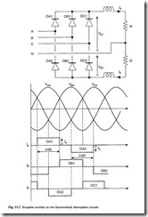
Connecting two three-pulse circuits, one operating on the positive half cycle and the other on the negative half cycle, in a back-to-back configuration forms the six-pulse rectifier, as shown in Fig. 11.2. The upper three-pulse rectifier here is identical to that described in section 11.2.1, whilst the lower circuit is essentially formed from the first by reversing the diodes, enabling it to operate on the negative parts of the supply voltage waveform.
Since the average values of vD1 and vD2 are the same, the currents in the two load resistors will be the same, provided that these have equal values R. Under these conditions, the line currents will consist of 120° pulses of +Io as DA1, DB1 and DC1 conduct, and 120° pulses of –Io as DA2, DB2 and DC2 conduct. The negative pulses will flow between the positive pulses, making the line currents quasi-squarewaves.
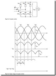
Furthermore, since the two resistors carry equal currents, the neutral current will be zero, and the neutral connection may be removed without affecting the circuit operation. This leaves the standard three-wire, six-pulse rectifier of Fig. 11.3, into which the load is simply drawn as a constant current element, representing its highly inductive nature.
Figure 11.4 shows the detail of the two three-pulse output voltages vD1 and vD2 and the total output voltage vDD = vD1 + vD2. Since the ripple components in vD1 and vD2 are phase-shifted by p/3 radians, the resultant ripple in vDD is reduced in amplitude and has a repetition interval of p/3 radians, giving six pulses per period of the input waveform. The average of vDD is simply twice the average value of the three-pulse waveforms and from eqn 11.1:
The six-pulse rectifier is widely used for the conversion of ac to dc, for example as the input stage of a variable speed induction motor drive system, described in Chapter 10.
Characteristics of the six-pulse input current
Fourier analysis of the quasi-squarewave currents drawn by the six-pulse rectifier shows that the harmonic amplitudes of the currents are given by eqn 11.3:
where n is the harmonic number. The fundamental component of each line current is in phase with the respective line-to-neutral voltage, as is evident from Fig. 11.2.
The following conclusions may be drawn from eqn 11.3:
● the fundamental current has an amplitude of 2
● there are no even harmonics 3 Io/p
● the sine function will be zero for n = 3, 9, 15, 21, …, therefore, the harmonics that are odd multiples of three, known as triplens, will also be zero Figure 11.5 shows the harmonic amplitudes of the quasi-squarewave current, normalized to the fundamental amplitude. The non-zero harmonics are of the order 6k ± 1, where k = 1, 2, 3, …. The rms value, IRMS of the quasi-squarewave rectifier input current in Fig. 11.2 is:
The active power transfer to loads that draw non-sinusoidal currents from a sinusoidal supply is solely due to the fundamental component of the current, and the six-pulse rectifier therefore has a power factor of less than unity even though the fundamental component of current is in phase with the voltage. The power factor of the six-pulse rectifier is given by eqns 11.5 and 11.6.
where IL(1)rms is the rms fundamental component of line current, ILrms is the rms line current and f1 is the phase angle of the fundamental current with respect to the voltage. Since f1 = 0, the power factor is:
The practical operation of the rectifier differs slightly from this idealized representation because of the presence of source inductance, which slows down the edges of the quasi-squarewave input currents and gives rise to an output voltage regulation effect. Ripple current in the dc inductor also modifies the shape of the input currents.
Twelve-pulse rectifier with delta–star transformer
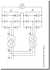
To enhance the characteristics of the six-pulse rectifier, reducing the input current harmonics and the output voltage ripple, multiple rectifiers may be combined with a phase-shifting device, a transformer or an autotransformer. As an example, Fig. 11.6
shows one of the simplest ways of combining two six-pulse rectifiers to produce a twelve-pulse circuit.
The first rectifier in Fig. 11.6 is supplied through a delta–star transformer, whilst the second operates through a delta–delta transformer. The turns ratio of the delta–star transformer is 1:1/ 3 , so the secondary line-to-line voltages have the same amplitude as the primary voltages, but are advanced in phase by 30°. The delta–delta transformer has a 1:1 turns ratio and its primary and secondary voltages and currents are identical, neglecting magnetizing current; it does not provide any phase shift. The two sets of transformer primaries are connected in parallel, whilst the rectifier outputs are connected in series across a common load. This results in the two six-pulse rectifiers delivering the same load current. The two transformers could be replaced by a single device having two sets of secondaries; one connected in star, the other in delta.
Figure 11.7 shows the current waveforms for the first supply line in the twelve- pulse rectifier. The diagram shows that in the two six-pulse rectifiers, each draw quasi- squarewave currents of value ± Io, iX1 and iX2 being the currents in the first input line to each rectifier. A phase shift of p/6 radians or 30° is shown between the two currents, iX1 is leading iX2 due to the 30° phase advance in the input voltage waveforms to the first rectifier, which is provided by the delta–star transformer.
The first transformer input current, iA1, is formed by the combination of two reflected quasi-squarewave secondary currents, (iX1 – iZ1)/ 3 . The second transformer input current, iA2, is the same as the secondary current iX2, since this transformer is a simple delta–delta configuration. The resultant current drawn from the utility is iA = iA1 + iA2, and is seen to have a multi-level stepped shape somewhat closer to the ideal of a sinewave than either iA1 or iA2.
Due to the 30° phase shift between the two rectifiers, their six-pulse ripples will be out of phase, resulting in an overall output voltage which has a smaller ripple, the ripple frequency being twelve times the supply frequency. Analysis of the twelve-pulse current waveform reveals that the non-zero harmonics are now 1, 11, 13, 23, 25, …, that is of order 12k ± 1 where k = 1, 2, 3, …. The power factor of the twelve-pulse rectifier is increased to 0.9886 due to the reduced harmonic content of the input currents.
For lower output voltage and higher output current applications, the two rectifier outputs may be connected in parallel, however, an inter-phase reactor would normally then be used to prevent the circulation of currents between the two rectifiers. Twelve- pulse rectifiers would normally be used in higher power applications, or in environments having very stringent power quality specifications, such as an aircraft.
Controlled rectifiers
By replacing the diodes in the circuits described in the previous sections by thyristor devices, the output voltage of the rectifiers may be controlled, and a reversal of power flow is also possible if a source of energy is present in the dc circuit. The thyristor is a comparatively old power device that has limited control characteristics. A gate pulse must be applied to the control terminal to switch the device into its conducting state, however, once the device is in conduction it cannot be turned off and will only return to the off state when the circuit current naturally falls to zero.
The operating principle of thyristor-controlled rectifiers is illustrated using the three-pulse circuit in Fig. 11.1. The waveforms with thyristor control are shown in Fig. 11.8. As before, each device conducts the dc load current in sequence for one-third of the supply cycle, however, the conduction of each device is delayed by the firing delay angle a. This results in the output voltage vD being modified. The average value of vD is given by eqn 11.7:
The average output voltage falls to zero as a is increased to 90°. If a source of emf is present in the dc circuit, orientated to maintain the current flow, then a may be increased beyond 90° and the circuit enters the inversion mode of operation. The aver- age value of VD becomes negative, but the direction of current in the dc circuit is unchanged, and power flows from the energy source in the dc circuit into the ac system. To reverse the dc circuit current and obtain four-quadrant operation of the output, two rectifier circuits must be used in a back-to-back configuration.
The output voltage of the six- and twelve-pulse rectifiers may be controlled in a similar manner. However, a disadvantage of this mode of operation is that it results in a phase shift of the input currents, reducing the power factor. Thyristor-controlled rectifiers are widely used for the control of dc motor drives, as described in section 10.10.1.


