Grounding Equipment Racks
The installation and wiring of equipment racks must be planned carefully to avoid problems during day- to-day operations. Figure 20.28 shows the recommended approach. Bond adjacent racks together with 3/ 8- to 1/2-in.-diameter bolts. Clean the contacting surfaces by sanding down to bare metal. Use lockwashers on both ends of the bolts. Bond racks together using at least six bolts per side (three bolts for each vertical rail). After securing the racks, repaint the connection points to prevent corrosion.
Run a ground strap from the main facility ground point, and bond the strap to the base of each rack. Spot-weld the strap to a convenient spot on one side of the rear portion of each rack. Secure the strap at the same location for each rack used. A mechanical connection between the rack and the ground strap can be made using bolts and lockwashers, if necessary. Be certain, however, to sand down to bare metal before making the ground connection. Because of the importance of the ground connection, it is recom- mended that each attachment be made with a combination of crimping and silver-solder. Keep the length of strap between adjacent bolted racks as short as possible by routing the strap directly under the racks.
Install a vertical ground bus in each rack (as illustrated in Figure 20.28). Use about 1-1/2-in.-wide, 1/ 4-in.-thick copper busbar. Size the busbar to reach from the bottom of the rack to about 1 ft short of the top. The exact size of the busbar is not critical, but it must be sufficiently wide and rigid to permit the drilling of 1/8-in. holes without deforming.
Mount the ground busbar to the rack using insulated standoffs. Porcelain standoffs commonly found in high-voltage equipment are useful for this purpose. Porcelain standoffs are readily available and reasonably priced. Attach the ground busbar to the rack at the point that the facility ground strap attaches to the rack. Silver-solder the busbar to the rack and strap at the same location in each rack used.
Install an orange-type isolated ac receptacle box at the bottom of each rack. The orange-type outlet isolates the green-wire power ground from the receptacle box. Use insulated standoffs to mount the ac outlet box to the rack. The goal of this arrangement is to keep the green-wire ac and facility system grounds separate from the ac distribution conduit and metal portions of the building structure. Try to route the power conduit and facility ground cable or strap via the same physical path. Keep metallic con- duit and building structures insulated from the facility ground line, except at the bulkhead panel (main grounding point). Carefully check the local electrical code before proceeding.
Although the foregoing procedure is optimum from a signal-grounding standpoint, it should be pointed out that under a ground-fault condition, performance of the system can be unpredictable if high currents are being drawn in the current-carrying conductors supplying the load. Vibration of ac circuit elements resulting from the magnetic field effects of high-current-carrying conductors is insignificant as long as all conductors are within the confines of a given raceway or conduit. A ground fault will place return current outside of the normal path. If sufficiently high currents are being conducted, the consequences can be devastating. Sneak currents from ground faults have been known to destroy wiring sys- tems that were installed exactly to code. As always, consult an experienced electrical contractor.
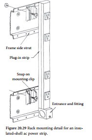
Mount a vertical ac strip inside each rack to power the equipment. Insulate the power strip from the rack using porcelain standoffs or use a strip with an insulated (plastic) housing. Such a device is shown in Figure 20.29. Power equipment from the strip using standard three-prong grounding ac plugs. Do not defeat the safety ground connection. Equipment manufacturers use this ground to drain transient energy.
Furthermore, defeating the safety ground will violate local electrical codes.
Mount equipment in the rack using normal metal mounting screws. If the location is in a high-RF field, clean the rack rails and equipment-panel connection points to ensure a good electrical bond. This is important because in a high-RF field, detection of RF energy can occur at the junctions between equipment chassis and the rack.
Connect a separate ground wire from each piece of equipment in the rack to the vertical ground busbar. Use no. 12 or larger stranded copper wire (insulated). Connect the ground wire to the busbar by drilling a hole in the busbar at a convenient elevation near the equipment. Fit one end of the ground wire with an enclosed-hole solderless terminal connector (no. 10- sized hole or larger). Attach the ground wire to the busbar using no. 10 (or larger) hardware. Use an internal-tooth lockwasher between the busbar and the nut. Fit the other end of the ground wire with a termi- nal that will be accepted by the ground terminal at the equipment. If the equipment has an isolated signal ground terminal, tie it to the ground busbar, as well.
Whenever servicing equipment in the rack, make certain to disconnect the ac power cord before removing the unit from the rack or disconnecting the rack ground wire. During any service work, make the first step removal of the ac power plug; when reassembling the unit, make the last step reinsertion of the plug. Do not take chances.
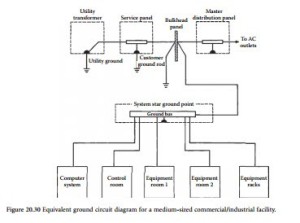
Figure 20.30 shows each of the grounding elements discussed in this section integrated into one diagram. This approach fulfills the requirements of personnel safety and equipment performance.
Follow similar grounding rules for simple one-rack equipment installations. Figure 20.31 illustrates the grounding method for a single open-frame equipment rack. The vertical ground bus is supported by insulators, and individual jumpers are connected from the ground rail to each chassis.

