Understanding Ground Resistance
The term ground is defined as a conducting connection by which a circuit or equipment is connected to the earth. The connection is used for establishing and maintaining as closely as possible the potential of the earth on the circuit or equipment connected to it. A ground consists of a grounding conductor, a bonding connector, its grounding electrode(s), and the soil in contact with the electrode.
Grounds have several fundamental protection applications. For natural phenomena, such as lightning, grounds are used to provide a discharge path for the current to reduce shock hazard to personnel and to prevent damage to equipment and property.
For induced potentials due to faults in electric power systems with ground returns, grounds help in ensuring rapid operation of the protection relays by providing low resistance fault current paths. This provides for the removal of the induced potential as quickly as possible. The ground should drain the induced potential before personnel are injured and the power or communi- cations system is damaged.
Ideally, to maintain a reference potential for instrument safety, to protect against static electricity, and limit the equipment ground voltage for operator safety, a ground resistance should be 0 Ω. In reality, as explained in this text this value cannot be achieved. However, low ground resistance is required by NEC, OSHA, and other electrical safety codes and standards.
Grounding Electrode Resistance
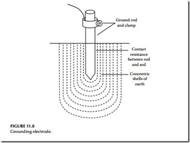
Figure 11.8 illustrates a grounding rod (electrode). The resistance of the grounding is made up of the following components:
1. Resistance of the electrode itself and that of the connection to it
2. Contact resistance of the surrounding earth to the electrode
3. Resistance of the earth immediately surrounding the grounding electrode or resistivity of earth, which is often the most significant factor
The grounding electrodes are usually made of a very conductive metal (copper or copper clad) with adequate cross sections so that the overall resistance is negligible. The resistance between the electrode and the surrounding earth is negligible if the electrode is free of paint, grease, or other coating, and if the earth is firmly packed.
The only component remaining is the resistance of the surrounding earth. The electrode can be thought of as being surrounded by concentric shells of earth or soil, all of the same thickness. The closer the shell to the electrode, the smaller its surface; hence, the greater its resistance. The farther away the shells are from the electrode, the greater the surface of the shell; hence, the lower the resistance. Eventually, adding shells at a distance from the grounding elec- trode will no longer noticeably affect the overall earth resistance surrounding the electrode. The distance at which this effect occurs is referred to as the effective resistance area and is directly dependent on the depth of the grounding electrode.
When ground fault current flows from a ground rod to earth, it flows in all directions through a series of concentric spheres or shells, commonly referred to as effective cylinders of earth, surrounding the rod. The resistance of the closest sphere to the ground rod is the highest because it is the smallest sphere.
As the distance from the ground rod is increased, the resistance becomes less because the sphere becomes larger. Eventually, a distance from the electrode is reached where the sphere resistance becomes zero. Therefore, in any ground resistance measurement only the part of earth resistance is considered that contributes a major part of the resistance. Theoretically, the earth resistance of the ground system should be measured up to infinite distance from the ground rod. However for practical purposes, the effective cylinder of earth (shells) that contributes the major portion of the earth resistance is two times the length of the ground rod.
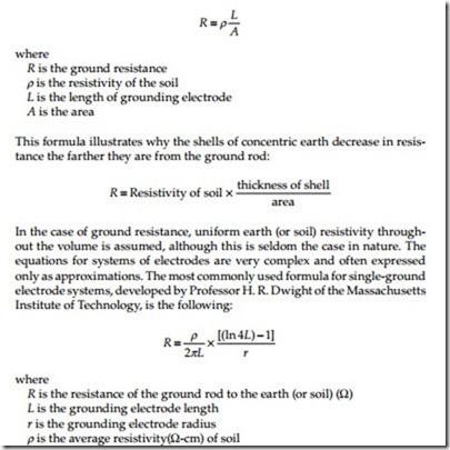
In theory, the ground resistance may be derived from the general formula:
Effect of Ground Electrode Size and Depth on Resistance
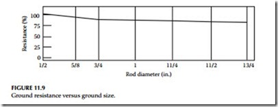
Size: Increasing the diameter of the rod does not materially reduce its resis- tance. Doubling the diameter of the ground rod reduces resistance by less than 10%, as indicated in Figure 11.9.
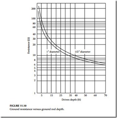
Depth: As a ground rod is driven deeper into the earth, its resistance is substantially reduced. In general, doubling the rod length reduces the resistance by an additional 40%, as seen in Figure 11.10. The NEC requires a minimum of 8 ft (2.4 m) to be in contact with the soil. The most common is a 10 ft (3 m) cylindrical rod which meets the NEC code. A minimum diameter of 5/8 in. (1.59 cm) is required for steel rods and 1/2 in. (1.27 cm) for copper
Effect of Soil Resistivity on Ground Electrode Resistance
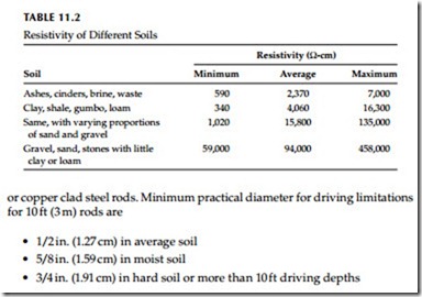
Dwight’s formula, cited previously, shows that the resistance of grounding electrodes to earth depends not only on the depth and surface area of ground- ing electrodes, but on soil resistivity as well. Soil resistivity is the key factor that determines what the resistance of a grounding electrode will be, and to what depth it must be driven to obtain low ground resistance. The resistivity of the soil varies widely throughout the world and changes seasonally. Soil resistivity is determined largely by its content of electrolytes, consisting of moisture, minerals, and dissolved salts. A dry soil has high resistivity if it contains no soluble salts, as shown in Table 11.2.
Factors Affecting Soil Resistivity
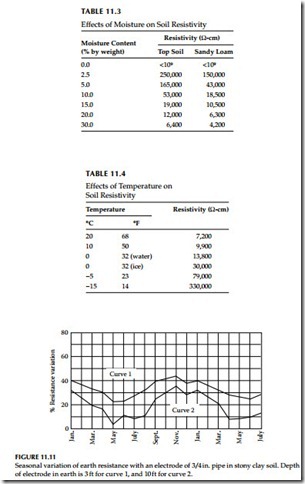
Two samples of soil, when thoroughly dried, may become in fact very good insulators, having a resistivity in excess of 109 Ω-cm. The resistivity of the soil sample is seen to change quite rapidly until approximately 20% or greater moisture content is reached as indicated in Table 11.3.
The resistivity of the soil is also influenced by temperature. Table 11.4 shows the variation of resistivity of sandy loam, containing 15.2% moisture, with temperature changes from 20°C to –15°C. In this temperature range, the resistivity is seen to vary from 7,200 to 330,000 Ω-cm.
Because soil resistivity directly relates to moisture content and temperature, it is reasonable to assume that the resistance of any grounding system will vary throughout the different seasons of the year. Such variations are shown in Figure 11.11. Since both temperature and moisture content become more stable at greater distances below the surface of the earth, it follows
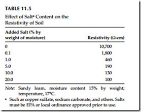
a Such as copper sulfate, sodium carbonate, and others. Salts must be EPA or local ordinance approved prior to use.
that a grounding system to be most effective at all times should be con- structed with the ground rod driven down a considerable distance below the surface of the earth. Best results are obtained if the ground rod reaches the water table.
In some locations, the resistivity of the earth is so high that low-resistance grounding can be obtained only at considerable expense and with an elabo- rate grounding system. In such situations, it may be economical to use a ground rod system of limited size and to reduce the ground resistivity by periodically increasing the soluble chemical content of the soil. Table 11.5 shows the substantial reduction in resistivity of sandy loam brought about by an increase in chemical salt content.
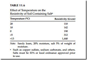
Chemically treated soil is also subject to considerable variation of resistivity with changes in temperature, as shown in Table 11.6. If salt treatment is employed, it is, of course, necessary to use ground rods that will resist corrosion.
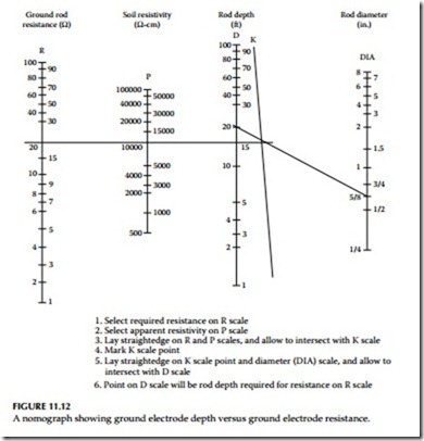
1. Select required resistance on R scale
2. Select apparent resistivity on P scale
3. Lay straightedge on R and P scales, and allow to intersect with K scale
4. Mark K scale point
5. Lay straightedge on K scale point and diameter (DIA) scale, and allow to
intersect with D scale
6. Point on D scale will be rod depth required for resistance on R scale
FIGURE 11.12
A nomograph showing ground electrode depth versus ground electrode resistance.
Effect of Ground Electrode Depth on Resistance
In determining the approximate ground rod depth required to obtain a desired resistance, a grounding nomograph may be used. The nomograph, shown in Figure 11.12, indicates that to obtain a grounding resistance of 20 Ω in a soil with a resistivity of 10,000 Ω-cm, a 5/8 in. OD rod must be driven 20 ft. Note that the values indicated on the nomograph are based on the assumption that the soil is homogenous and, therefore, has uniform resistivity. The nomograph value is an approximation.
