Fall-of-Potential Method
This method measures grounding electrode resistance based upon the principle of potential drop across the resistance. It also uses two auxiliary electrodes (one current rod and the other a potential rod) that are placed at a sufficient distance from the test electrodes; a current of known magnitude is passed through the electrode under test and one of the auxiliary electrodes (current rod). The drop in potential between the electrode under the test and the second auxiliary electrode (potential rod) is measured. The ratio of volt- age drop (V) to the known current (I) will indicate the resistance of the grounding circuit. Either a DC or AC voltage source may be used for con- ducting this test.
Several problems and errors may be encountered with this method, such as (i) stray currents in earth may cause voltmeter readings to be either high or low and (ii) the resistance of auxiliary electrode and electrical leads may introduce errors in the voltmeter reading. This error can be minimized by using a voltmeter of high impedance value.
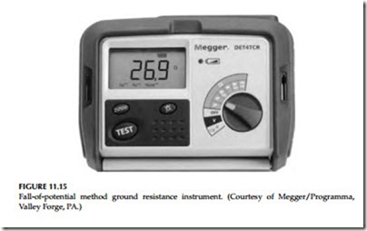
This method can be used with either a separate voltmeter and ammeter or a single instrument which provides a reading directly in ohms (see Figure 11.15). To measure the resistance of a grounding electrode, the current electrode is placed at a suitable distance from the grounding electrode under test. As shown in Figure 11.16, the potential difference between rods X and Y is measured by a voltmeter, and the current flow between rods X and Z is measured by an ammeter. (Note: X, Y, and Z may be referred to as X, P, and C in a three-point tester or C1, P2, and C2 in a four-point tester.)
Position of the Auxiliary Electrodes on Measurements
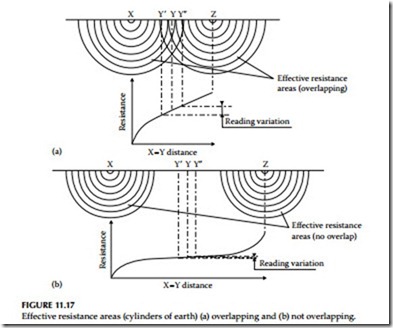
The goal in precisely measuring the resistance to ground is to place the auxiliary current electrode Z far enough from the ground electrode under test so that the auxiliary potential electrode Y will be outside of the effective resistance areas (effective cylinder of earth) of both the ground electrode and the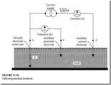
Effective resistance areas (cylinders of earth) (a) overlapping and (b) not overlapping.
auxiliary current electrode. The best way to find out if the auxiliary potential rod Y is outside the effective resistance areas is to move it between X and Z and to take a reading at each location. If the auxiliary potential rod Y is in an effective resistance area (or in both if they overlap as in Figure 11.17a), by displacing it the readings taken will vary noticeably in value. Under these conditions, no exact value for the resistance to ground may be determined.
On the other hand, if the auxiliary potential rod Y is located outside of the effective resistance areas, as in Figure 11.17b, as Y is moved back and forth the reading variation is minimal. The readings taken should be relatively close to each other, and are the best values for the resistance to ground of the ground X. The readings should be plotted to ensure that they lie in a “plateau” region as shown in Figure 11.17b. The region is often referred to as the 62% area which is discussed in the following section.
Measuring Resistance of Ground Electrodes (62% Method)
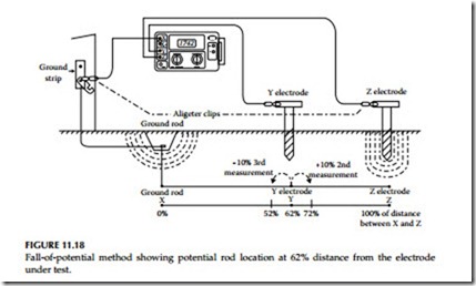
The 62% method is an extension of the fall-of-potential method and has been adopted after graphical consideration and after actual test. It is the most accurate method but is limited by the fact that the ground tested is a single unit. This method applies only when all three electrodes are in a straight line and the ground is a single electrode, pipe, or plate, etc., as is shown in Figure 11.18.
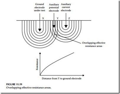
Consider Figure 11.19, which shows the effective resistance areas (concentric shells) of the ground electrode X and of the auxiliary current electrode Z. The effective cylinders of earth of the X and Z rods overlap. If readings were taken by moving the auxiliary potential electrode Y toward either X or Z,
the reading differentials would be great and one could not obtain a reading within a reasonable band of tolerance. The sensitive areas overlap and act constantly to increase resistance as Y is moved away from X.
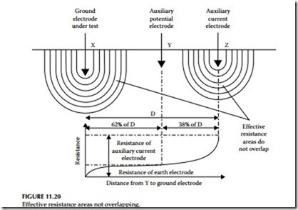
Now consider Figure 11.20, where the X and Z electrodes are sufficiently spaced so that the areas of effective resistance do not overlap. If we plot the resistance measured, we find that the measurements level off when Y is placed at 62% of the distance from X to Z, and that the readings on either side of the initial Y setting are most likely to be within the established tolerance band. This tolerance band is defined by the user and expressed as a percent of the initial reading: ±2%, ±5%, ±10%, etc.
Auxiliary Electrode Spacing
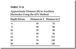
No definite distance between X and Z can be given, since this distance is relative to the diameter of the electrode tested, its length, the homogeneity of the soil tested, and particularly, the effective resistance areas. However, an approximate distance may be determined from Table 11.8, which is given for a homogeneous soil and an electrode of 1 in. in diameter. (For a diameter of 1/2 in., reduce the distance by 10%; for a diameter of 2 in. increase the distance by 10%.) It is recommended that the test should be made for ground elec- trode resistance for each season of the year. The data should be retained for each season for comparison and analysis. Serious deviation of the test data from previous years, other than seasonal variations, could mean electrode corrosion.
Multiple Electrode System
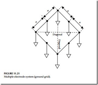
A single driven ground electrode is an economical and simple means of making a good ground system. But sometimes a single rod will not provide sufficient low resistance, and several ground electrodes will be driven and connected in parallel by a cable. Very often when two, three, or four ground electrodes are used, they are driven in a straight line; when four or more are used, a hollow square configuration is used and the ground electrodes are still connected in parallel and equally spaced as shown in Figure 11.21.
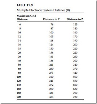
In multiple electrode systems, the 62% method electrode spacing may no longer be applied directly (see Table 11.9). The distance of the auxiliary electrodes is now based on the maximum grid distance (i.e., in a square, the
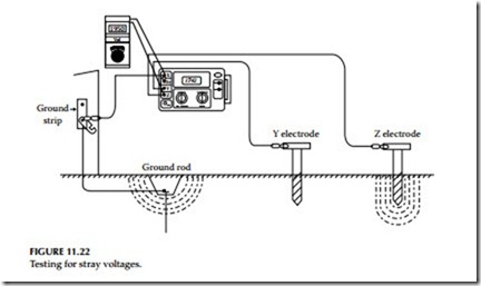
Excessive noise. Excessive noise may interfere with testing because of the long leads used to perform a fall-of-potential test. A voltmeter can be utilized to identify this problem. Connect the X, Y, and Z cables to the auxiliary electrodes as for a standard ground resistance test. Use the voltmeter to test the voltage across terminals X and Z as shown in Figure 11.22. The voltage reading should be within the stray voltage tolerances acceptable to the ground tester being used. If the test exceeds this value, try the following techniques:
1. Braid the auxiliary cables together. This often has the effect of canceling out the common mode voltages between these two conductors.
2. If the previous method fails, try changing the alignment of the auxiliary cables so that they are not parallel to power lines above or below the ground.
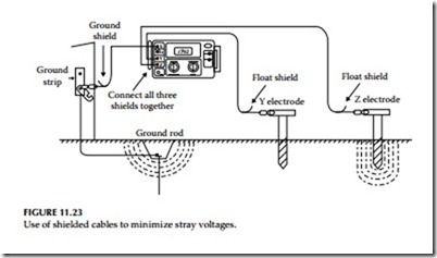
3. If a satisfactory low voltage value is still not obtained, the use of shielded cables may be required. The shield acts to protect the inner conductor by capturing the voltage and draining it to ground, as shown in Figure 11.23.
Excessive auxiliary rod resistance. The inherent function of a fall-of-potential ground tester is to input a constant current into the earth and measure the voltage drop by means of auxiliary electrodes. Excessive resistance of one or both auxiliary electrodes can inhibit this function. This is caused by high soil resistivity or poor contact between the auxiliary electrode and the sur- rounding dirt. To ensure good contact with the earth, stamp down the soil directly around the auxiliary electrode to remove air gaps formed when inserting the rod. If soil resistivity is the problem, pour water around the auxiliary electrodes. This reduces the auxiliary electrode’s contact resistance without affecting the measurement.
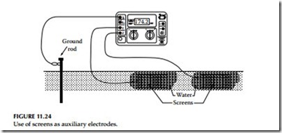
Tar or concrete mat. Sometimes a test must be performed on a ground rod that is surrounded by a tar or concrete mat, where auxiliary electrodes cannot be driven easily. In such cases, metal screens and water can be used to replace auxiliary electrodes, as shown in Figure 11.24. Place the screens on the floor the same distance from the ground rod under test as you would auxiliary electrodes in a standard fall-of-potential test. Pour water on the screens and allow it to soak in. These screens will now perform the same function as would driven auxiliary electrodes.
Ratio Method
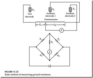
This method uses a Wheatstone bridge or an ohmmeter to measure the series resistance of grounding electrode and the auxiliary electrode. The test connections are shown in Figure 11.25. A slide wire potentiometer is used with a Wheatstone bridge for this test. The potentiometer is connected across the grounding electrode under test and the first auxiliary electrode. The sliding contact of the potentiometer is connected to the second auxiliary electrode through a detector for determining the null point. The resistance of the test electrode and first auxiliary electrode is measured first by the Wheatstone bridge or ohmmeter. Then, using the potentiometer and Wheatstone bridge, a new null point is determined with the second electrode in the test circuit. The resistance of the grounding electrode is the ratio of the test electrode resistance to the total resistance of the two in series. The procedure and equations are as follows:
• Measure Rx + Ry by means of a Wheatstone bridge or ohmmeter
• Determine from the potentiometer the ratio of RA/(RA + RB)
• Insert second auxiliary electrode (Rz) in test circuit and obtain null point

