Fusing and Protection
The main purpose of the fuse on a capacitor bank is to clear a fault if a capacitor unit or any of the accessories fail. The fuse must clear the fault quickly to prevent any of the equipment from failing violently. Ruptures of capacitors have historically been problematic, so fusing is normally tight. Fuses must be sized to withstand normal currents, including harmonics.
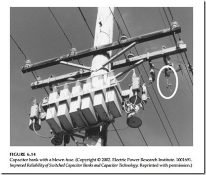
A significant number of utilities have problems with nuisance fuse oper- ations on capacitor banks. A fuse is blown, but the capacitors themselves are still functional. These blown fuses may stay on the system for quite some time before they are noticed (see Figure 6.14). Capacitors with blown fuses increase voltage unbalance, can increase stray voltages, and increase losses. Even if the capacitor controller identifies blown fuses, replacement adds extra maintenance that crews must do.
Improved Reliability of Switched Capacitor Banks and Capacitor Technology. Reprinted with permission.)
IEEE guides suggest selecting a fuse capable of handling 1.25 to 1.35 times the nominal capacitor current (IEEE Std. C37.48-1997); a 1.35 factor is most common. Three factors can contribute to higher than expected current:
• Overvoltage — Capacitive current increases linearly with voltage, and the reactive vars increase as the square of the voltage. When esti- mating maximum currents, an upper voltage limit of 110% is nor- mally assumed.
• Harmonics — Capacitors can act as a sink for harmonics. This can increase the peak and the rms of the current through the capacitor. Additionally, grounded three-phase banks absorb zero-sequence harmonics from the system.
• Capacitor tolerance — Capacitors were allowed to have a tolerance to
+15% above their rating (which would increase the current by 15%).
Most fusing practices are based on fusing as tightly as possible to prevent case rupture. So, the overload capability of fuse links is included in fuse sizing. This effectively allows a tighter fusing ratio. K and T tin links can be overloaded to 150%, so for these links with a 1.35 safety factor, the smallest size fuse that can be used is
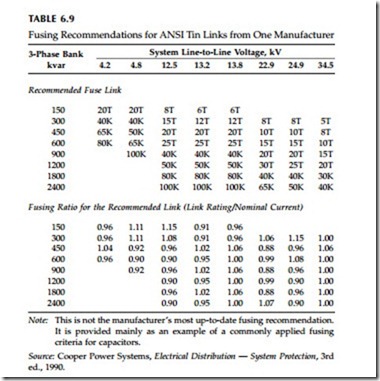
Table 6.9 shows one manufacturer’s recommendations based on this tight- fusing approach.
With this tight-fusing strategy, fuses must be used consistently. If silver links are used instead of tin links, the silver fuses can blow from expected levels of current because silver links have no overload capability.
Prior to the 1970s, a fusing factor of 1.65 was more common. Due to concerns about case ruptures and PCBs, the industry went to tighter fusing factors, 1.35 being the most common. Because of the good performance of all-film capacitors and problems with nuisance fuse operations, consider a
looser fusing factor, possibly returning to the 1.65 factor. Slower fuses should also have fewer nuisance fuse operations.
Capacitors are rated to withstand 180% of rated rms current, including fundamental and harmonic currents. Fusing is normally not based on this limit, and is normally much tighter than this, usually from 125 to 165% of rated rms current. Occasionally, fuses in excess of 180% are used. In severe harmonic environments (usually in commercial or industrial applications), normally fuses blow before capacitors fail, but sometimes capacitors fail before the fuse operates. This depends on the fusing strategy.
If a capacitor bank has a blown fuse, crews should test the capacitors before re-fusing. A handheld digital capacitance meter is the most common approach and is accurate. Good multimeters also can measure a capacitance high enough to measure the capacitance on medium-voltage units. There is a chance that capacitance-testers may miss some internal failures requiring high voltage to break down the insulation at the failure. Measuring the capacitance on all three phases helps identify units that may have partial failures. Partial failures show up as a change in capacitance. In a partial failure, one of several series capacitor packs short out; the remaining packs appear as a lower impedance (higher capacitance). As with any equipment about to be energized, crews should visually check the condition of the capacitor unit and make sure there are no bulges, burn marks, or other signs that the unit may have suffered damage.
Some utilities have problems with nuisance fuse operations on distribution transformers. Some of the causes of capacitor fuse operations could be the same as transformer fuse operations, but some differences are apparent:
• Capacitor fuses see almost continuous full load (when the capacitor is switched in).
• Capacitor fuses tend to be bigger. The most common transformer sizes are 25 and 50 kVA, usually with less than a 15 A fuse. Typical capacitor sizes are 300 to 1200 kvar with 15 to 65 A fuses.
• Both have inrush; a capacitor’s is quicker.
• Transformers have secondary faults and core saturation that can contribute to nuisance fuse operations; capacitors have neither.
Some possible causes of nuisance fuse operations are
• Lightning — Capacitors are a low impedance to the high-frequency lightning surge, so they naturally attract lightning current, which can blow the fuse. Smaller, faster fuses are most prone to lightning. Given that the standard rule of thumb that a fuse at least as big as a 20K or a 15T should prevent nuisance operations, it is hard to see how lightning itself could cause a significant number of fuse oper- ations (as most capacitor bank fuses are larger than this).
• Outrush to nearby faults — If a capacitor dumps its stored charge into a nearby fault, the fuse can blow. Capacitor banks also have inrush every time they are switched in, but this is well below the melt point of the fuse.
• Severe harmonics — Harmonics increase the current through the fuse.
• Animal or other bushing faults — A fault across a bushing due to an animal, contamination on the bushing, or tree contact can blow a fuse. By the time anyone notices the blown fuse, the squirrel or branch has disappeared. Use animal guards and covered jumpers to reduce these.
• Mechanical damage and deterioration — Corrosion and vibration can weaken fuse links. On fuse links collected from the field on trans- formers, Ontario Hydro found that 3% had broken strain wires (CEA 288 D 747, 1998). Another 15% had braids that were brittle and had broken strands. Larger fuses used in capacitors should not have as much of a problem.
• Installation errors — Fuses are more likely to blow if crews put in the wrong size fuse or wrong type fuse or do not properly tighten the braid on the fuse.
Outrush is highlighted as a possible failure mode that has been neglected by the industry. Outrush is sometimes considered for station banks to calculate the probability of a fuse operation from a failure of an adjacent parallel unit. But for distribution fuses, nearby faults have not been considered in regard to the effects on fuse operations.
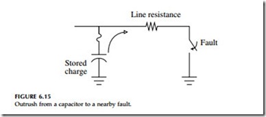
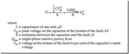
The energy input into the fuse during outrush depends on the line resistance between the capacitor and the fault (see Figure 6.15). The capacitor has stored energy; when the fault occurs, the capacitor discharges its energy into the resistance between the capacitor and the fault. Closer faults cause more energy to go into the fuse. The I2t that the fuse suffers during outrush to a line-to-ground fault is
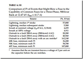
Table 6.10 shows several sources of fuse operations and the I2t that they generate for a 900-kvar bank at 12.47 kV. The nominal load current is 41.7
A. Utilities commonly use 40 or 50-A fuses for this bank. The table shows the minimum melt I2t of common fuses. Outrush to nearby faults produces high enough energy to blow common fuses, especially the K links. Of the other possible causes of fuse operation, none are particularly high except for a lightning first stroke. The lightning data is misleading because much of the first stroke will go elsewhere — usually, the line flashes over, and much of the lightning current diverts to the fault.
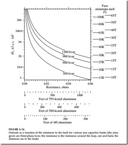
Use Figure 6.16 to find outrush I2t for other cases. Two factors make outrush worse:
• Higher system voltages — The outrush I2t stays the same with increases in voltage for the same size capacitor bank. The line imped- ance stays the same for different voltages. But higher-voltage capac-
itor banks use smaller fuses, with less I2t capability. So, a 25-kV capacitor installation is more likely to have nuisance fuse operations than a 12.5-kV system.
• Larger conductors — Lower resistance.
Consider a 1200-kvar bank with 500-kcmil conductors. At 12.47 kV (Iload = A) with a 65K fuse, the fuse exceeds its minimum melt I2t for faults up to 150 ft away. At 24.94 kV (Iload = 27.8 A) with a 30K fuse, the fuse may melt for faults up to 650 ft away. At 34.5 kV (Iload = 20.1 A) with a 25 K fuse, the location is off of the chart (it is about 950 ft). Note that the distance scales in Figure 6.16 do not include two important resistances: the capacitor’s internal resistance and the fuse’s resistance. Both will help reduce the I2t. Also, the minimum melt I2t values of the fuses in Figure 6.16 are the 60-Hz values. For high-frequency currents like an outrush discharge, the minimum melt I2t of expulsion fuses is 30 to 70% of the 60-Hz I2t (Burrage, 1981).
As an estimate of how much outrush contributes to nuisance fuse opera- tions, consider a 900-kvar bank at 12.47 kV with 40K fuses. We will estimate that the fuse may blow or be severely damaged for faults within 250 ft (76 m). Using a typical fault rate on distribution lines of 90 faults/100 mi/year (56 faults/100 km/year), faults within 250 ft (75 m) of a capacitor occur at the rate of 0.085 per year. This translates into 8.5% fuse operations per capacitor bank per year, a substantial number.
The stored energy on the fault depends on the timing of the fault relative to the point on the voltage wave. Unfortunately, most faults occur at or near the peak of the sinusoid.
Several system scenarios could make individual instances worse; most are situations that leave more than normal voltage on the capacitor before it discharges into the fault:
• Regulation overvoltages — Voltages above nominal increase the out- rush energy by the voltage squared.
• Voltage swells — If a line-to-ground fault on one phase causes a voltage swell on another and the fault jumps to the “swelled” phase, higher-than-normal outrush flows through the fuse.
• Arc restrikes — If a nearby arc is not solid but sputters, arc restrikes, much like restrikes of switches, can impress more voltage on the capacitor and subject the fuse to more energy, possibly much larger voltage depending on the severity. (I know of no evidence that this occurs regularly; most arcs are solid, and the system stays faulted once the arc bridges the gap.)
• Lightning — A nearby lightning strike to the line can charge up the capacitor (and start the fuse heating). In most cases, the lightning will cause a nearby flashover, and the capacitor’s charge will dump right back through the fuse.
• Multiple-phase faults — Line-to-line and three-phase faults are more severe for two reasons: the voltage is higher, and the resistance is lower. For example, on a line-to-line fault, the voltage is the line-to- line voltage, and the resistance is the resistance of the phase wires (rather than the resistance of a phase wire and the neutral in series).
These estimates are conservative in that they do not consider skin effects, which have considerable effect at high frequencies. Skin effects increase the conductor’s resistance. The transients oscillate in the single-digit kilohertz range. At these frequencies, conductor resistance increases by a factor of two
to three. On the negative side, the fuse element is impacted by skin effects, too — higher frequency transients cause the fuse to melt more quickly.
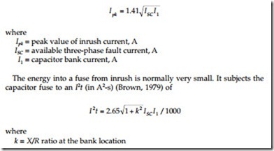
Capacitors also have inrush every time they are energized. Inrush into grounded banks has a peak current (IEEE Std. 1036-1992) of
Inrush is much worse if a capacitor is switching into a system with a nearby capacitor. The outrush from the already-energized bank dumps into the capacitor coming on line. Fuses at both banks see this transient. In substation applications, this back-to-back switching is a major design consideration, often requiring insertion of reactors between banks. For distribution feeder capac- itors, the design constraints are not as large. A few hundred feet of separation is enough to prevent inrush/outrush problems. For back-to-back switching, the I2t is almost the same as that for outrush:
The only difference is that the capacitance is the series combination of the two capacitances: C=C1C2/(C1+C2), and Qkvar=Q1Q2/(Q1+Q2). For the same size banks, C=C1/2, and Qkvar=Q1/2. Figure 6.16 applies if we double the kvar values on the curves. In most situations, maintaining a separation of 500 ft between capacitor banks prevents fuse operations from this inrush/outrush. Separate capacitor banks by 500 ft (150 m) on 15-kV class circuits to avoid inrush problems. Large capacitor banks on higher voltage distribution sys- tems may require modestly larger separations.
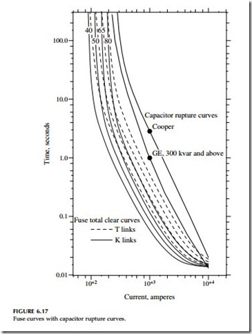
Preventing case ruptures is a primary goal of fusing. The fuse should clear before capacitor cases fail. Figure 6.17 shows capacitor rupture curves com- pared against fuse clearing curves. The graph shows that there is consider-
able margin between fuse curves and rupture curves. Consider a 12.47-kV, 900-kvar bank of three 300-kvar units, which has a nominal current of 41.7
A. Utilities commonly use a 40 or 50 K fuse for this bank. Larger fuses for this bank are possible, while still maintaining levels below case rupture curves. An EPRI survey found that case ruptures on modern film-foil capac- itors are rare (EPRI 1001691, 2002). This gives us confidence that we can loosen fusing practices without having rupture problems.
In areas of high fault current, current-limiting fuses provide extra safety. Either a backup current-limiting fuse in series with an expulsion link or a full-range current-limiting fuse is an appropriate protection scheme in high fault-current areas. While it may seem that expulsion fuses provide adequate protection even to 8 kA (depending on which rupture curve we use), current- limiting fuses provide protection for those less frequent faults with longer internal arcs. They also provide protection against failures in the capacitor switches and other capacitor-bank accessories. Utilities that apply current- limiting fuses on capacitors normally do so for areas with fault currents above 3 to 5 kA.
With backup current-limiting fuses, it is important that crews check the backup fuse whenever the expulsion link operates. On transformers, crews can get away with replacing the expulsion link. If the transformer still does not have voltage, they will quickly know that they have to replace the backup link. But, on capacitors, there is no quick indication that the backup- fuse has operated. Crews must check the voltage on the cutout to see if the backup fuse is operational; or crews should check the capacitor neutral current after replacing the expulsion link to make sure it is close to zero (if all three phases are operational, the balanced currents cancel in the neutral). In addition to not fixing the problem, failing to replace a blown backup fuse could cause future problems. The backup fuse is not designed to hold system voltage continuously — they are not an insulator. Eventually, they will track and arc over.
Because of utility problems with nuisance fuse operations, some loosening of fusing practices is in order. For most of the possible causes of nuisance- fuse operations, increasing the fuse size will decrease the number of false operations. Going to a slower fuse, especially, helps with outrush and other fast transients. If you have nuisance fuse operation problems, consider using T links and/or increase the fuse size one or two sizes. Treat these recommendations as tentative; as of this writing, these fusing issues are the subject of ongoing EPRI research, which should provide more definitive recommendations.
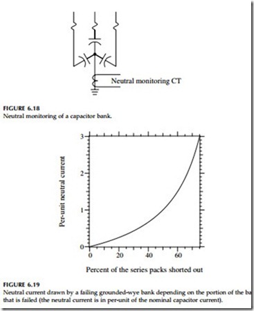
Neutral monitoring (Figure 6.18) is another protection feature that some capacitor controllers offer. Neutral monitoring can detect several problems:
• Blown fuse — When one capacitor fuse blows, the neutral current jumps to a value equal to the phase current.
• Failing capacitor unit — As a capacitor fails, internal groups of series packs short out. Prior to complete failure, the unit will draw more current than normal. Figure 6.19 shows how the neutral current changes when a certain portion of the capacitor shorts out. Capaci- tors rated from 7.2 to 7.96 kV normally have three or four series sections, so failure of one element causes neutral currents of 25% (for four in series) or 34% (for three in series) of the phase current.
Failure of more than half of the series sections causes more than the capacitor’s rated current in the neutral.
• High harmonic current — Excessive neutral current may also indicate high harmonic currents.
Neutral monitoring is common in substation banks, and many controllers for switched pole-mounted banks have neutral-monitoring capability. Neutral-current monitors for fixed banks are also available, either with a local warning light or a wireless link to a centralized location.
Neutral monitoring can help reduce operations and maintenance by eliminating regular capacitor patrols and field checks. Quicker replacement of blown fuses also reduces the time that excessive unbalance is present (and
the extra losses and possibility of stray voltage). This can lead to more reliable var regulation, and even reduce the number of capacitor banks needed.
