Case Study
Network Under Study
Fault current response of WTGs depends on the following factors;
• Short-circuit strength of WTG technology;
• Distance of WTG from PCC;
• System protection schemes;
• Voltage level of connection point; and
• System characteristics at that particular network region.
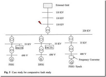
For weak system conditions, an individual distant wind farm connected to an HV system has been selected as case study in the scope of this chapter. To understand the response of each of the WTG technologies, a case study has been developed to carry out a comparative study for different WTG types. The network used for this case study is shown in Fig. 5. All the WTG types are connected under the same network conditions to provide a fair basis of comparison. All the models of this network are developed in DIgSILENT® Power Factory, and are lumped aggregated models. A strong external network having large short-circuit strength has been modeled but this has been separated by two long transmission lines. This is an attempt to create a weak network, as there is no conventional generation near the wind farms and the external infinite grid is separated by transmission lines. FSIG (Types-1 & 2) and DFIG (Type-3) wind farms are stepped up to a 0.69/33/ 220 kV voltage level to connect to point of common coupling (PCC). Full-scale frequency converter (FSFC) (Type-4) is stepped up to 0.4/33/220 kV voltage level to be connected to PCC. The voltage is further stepped down for transmission. Network and generators parameters are given as shown in the Appendix Tables A.1, A.2, A.3, and A.4. However, the system parameters are given in Table A.5 in Appendix A.