 TRANSIENTS, HARMONICS POWER FACTOR, AND FAILURES
Semiconductor Failure Rate
Although thyristors, diodes, and IGBTs are solid-state devices, they have wearout mecha- nisms just as insulation and other mechanical parts do. The wearout and failure rates of these devices can be calculated.
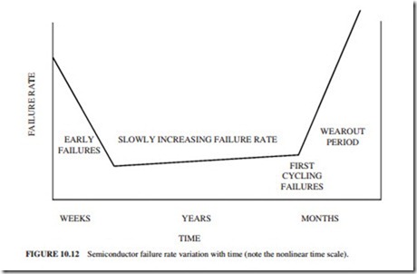
Figure 10.12 illustrates the general failure rate curve of SCRs, diodes, and IGBTs. The initial high failure rate is caused by manufacturing defects, application problems, and drive start-up stresses and lasts a few weeks. The high failure rate at the ends indicates the end of the life for the devices. In general, the lifetime of a device becomes shorter when it is operated harder and closer to its voltage rating.
Common Failure Modes
Differential Expansion (Mechanical Fatigue). This failure mode is mechanical fatigue or wearout caused by the difference in expansion rates as the temperature of the device changes. As the temperature of the device changes, different parts expand at different rates. These are the expansion coefficients for materials used in semiconductors:
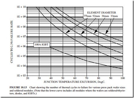
Thus, the parts slide over each other, causing mechanical wearout. This failure is common to all semiconductors. It normally occurs at the end of life of these devices. Figure 10.13 shows the thermal cycling fatigue life. Note the dependency on size and temperature. Also note that soldered modules are much worse than compressed ones. Although this module is labeled IGBT, in reality it applies to all modules having soldered terminals (i.e., thyristors, diodes, and transistors). It is important to note the low number of thermal cycles required for failure if the junction temperatures are allowed to climb too high.
Fault Current Limit. This mode of failure is not applicable to IGBTs because they are not able to conduct currents in excess of their ratings. It is only applicable to thyristors and diodes GTOs. The junction temperature increases when the fault current increases. The maximum surge current that can be tolerated results in junction temperature excursion l:lTj of 300°C. This temperature excursion can occur once in the lifetime of the equipment because it would have been damaged (maimed) by the high temperature. The number of current surges that can be tolerated increases rapidly if the peak current level (peak junction temperature) is reduced. The number of surges can be approximated by
This failure mode is normally caused by incorrect application. The designer of the system must ensure that the maximum fault current in the bridge cannot exceed these limits. This failure mode occurs normally during commissioning. However, it can occur at random intervals during the lifetime of the device.
Device Explosion Rating. This failure mechanism can occur in any of the power devices. Thyristors can break down in the reverse direction due to a fault. This is usually followed by a large surge current. The resulting arc at the edge of the device could be strong enough to blow open the ceramic housing. The explosion rating for a thyristor is normally 50 to 100 percent above the surge current rating.
This type of failure can have serious consequences because conductive plasma is vented from the failed cell into the bridge, resulting in extensive arcing and destruction through- out the whole bridge. These failures are normally caused by inadequate fault coordination (design deficiency). They usually occur during commissioning or at any time during the lifetime of the device.
Device Application. These failure modes normally occur in the middle region of Fig.
10.12 (slowly increasing failure rate) which extends over several years of operation. The failure rate depends on these application factors:
● Type of device application
● Voltage applied (as percentage of PIV)
● Junction temperature (at normal running load)
In general, the lifetimes of all semiconductors decrease when the applied voltage or tem- perature (as a percentage of the rating) increases.


