INVERTERS
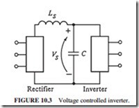
The main component of a VSD is the inverter. It is a power converter that converts the fixed ac input voltage and frequency to a controlled variable voltage and frequency to operate a motor at the required speed (Fig. 10.3). An energy storage device separates the input from the output and allows each to operate independently. It is called a link filter. The incoming power can be structured to give a very high power factor and low harmonics without affect- ing the output (we will only deal with voltage controlled inverters).
Parts of an Inverter
A normal ac inverter has three parts:
1. An input converter to rectify ac power to dc power. It is normally called the source bridge.
2. An energy storage device which separates the input from the output and allows each to operate independently from the other. It is usually called a link filter.
3. A dc-to-ac inverter in the output stage. It is called an inverter. It generates the desired ac output voltage and frequency.
Pulse-Width-Modulated Inverters
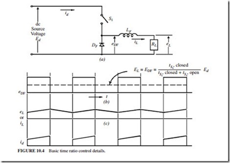
PWM is referred to as time ratio control. From a constant dc input voltage, we get a variable output voltage and frequency by varying the percentage of time that the power control switch is closed. The output voltage will increase by increasing the percentage of time the switch is closed. The switch is either open or closed. There is no power dissipation across the switch in both states. Figure 10.4 illustrates a PWM circuit.Please note
time while switch is closed + time while switch is open
The main parts of a PWM circuit are
● The input dc power.
● The power switch can be any semiconductor that we command to turn on or off.
● The inductor stores the energy from the switch when it is closed, then releases it to the load when the switch is opened.
● The freewheeling diode gives a path to the current to flow when the switch is opened. The stored energy in the inductor is released to the load.
Insulated Gate Bipolar Transistors. These bipolar power transistors are driven by an insulated gate metal-oxide transistor. A relatively simple 15-V gate driver signal is used to control the resulting high-current power transistor. The IGBT is a four-layer semiconduc- tor similar to the SCR. Its main features are that
1. It has very fast switching on the order of 100 to 150 ns (1 ns 10-9 s) and resulting high-voltage transients dυ/dt of 5000 to 10,000 V/j.Ls.
2. The IGBT chips are soldered in place and connected with discrete bond wires. They are very weak when it comes to thermal fatigue problems. The IGBT modules have significantly lower thermal fatigue capability than other semiconductors. The high dυ/dt generated leads to problems with bearing currents and the insulation system.
Two-Level Pulse-Width-Modulated Inverter (PWM-2). This is a voltage controlled inverter. It uses a bank of electrolytic capacitors to store the intermediate energy. Its ratings are up to 600 V ac and 1800 A. It is usually used to control an induction motor up to 60 Hz. However, it can be used to go up to 120 or even 150 Hz in special applications. Figure 10.3 illustrates a nonregenerative PWM drive that uses IGBTs in the output inverter.


