TEST DESCRIPTION AND SIGNIFICANCE
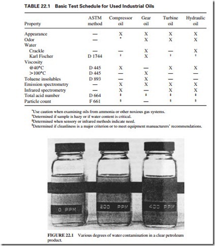
Table 22.1 lists the test schedule for used industrial oils.
Visual and Sensory Inspections
An experienced observer can determine if the oil has contamination or deterioration. Engine oils in short service or those exhibiting little degradation will have a bland or an additive odor similar to that of unused oil. Oils with longer service periods under favorable operating conditions have a normal “used” odor.
In the examination of compressor, turbine, and hydraulic systems, appearance and odor are particularly useful. These oils are bright and clear and have bland odor under favorable operating conditions. The oil becomes “hazy” in the presence of a small amount of sus- pended water. The oil will have a cloudy appearance when it has a larger amount of water (Fig. 22.1). The reference line behind the oil to the left is sharply defined. This confirms that the oil is dry and clear. The oil is hazy in the middle bottle containing 200 parts per million (ppm). The reference line behind the oil to the right can hardly be seen because the oil is so cloudy (containing 400 ppm of water). Larger quantities of water coalesce and form free water droplets which will settle at the bottom of the container. When contaminants increase in oil, its water separation properties gradually deteriorate. When there is contam- ination or oxidation in the oil, its color becomes significantly darker. The oil has charac- teristic odors under these conditions. Severe oxidation is characterized by a sharp or burnt odor. Some chemical contaminants have specific odors typical of fuel, chlorinated solvents,
or sour gas (i.e., a gas containing sulfur compounds). The oil analyst confirms these condi- tions by requesting additional tests.
Chemical and Physical Tests
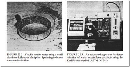
Water Content. The presence of water in oil is confirmed by a crackle test. A few drops of oil are placed in a small aluminum dish and heated rapidly over a small flame or on a laboratory hot plate (Fig. 22.2). The test can be conducted by using a hot electric soldering iron which is immersed in oil. If the water concentration is 0.01 percent or less, an audible crackling sound will be heard. When a crackle test confirms the presence of water, a quan- titative test is conducted by distillation (ASTM D95). The test involves dissolving a specific quantity of oil in a water-immiscible hydrocarbon solvent, such as xylene, and heated in a distillation flask. The water present in the oil co-distills with the solvent also. A condenser is used to cool the vapors. The water settles in the bottom of the trap where its volume can be measured, while the solvent flows back to the distillation flask.
Figure 22.3 illustrates an automated instrument used for the Karl Fisher method (ASTM D 1744). The advantage of this method is the ability to determine the amounts of free and dissolved water content in oil. However, it is normally used for relatively clean oils. This method is especially useful for refrigeration and hydraulic system lubricants which cannot have water content due to the potential damage of internal components. This is essential in refrigeration applications where free water droplets can freeze and plug the lubricant lines. The presence of water confirms lubricant contamination through leaking seals, coolant seepage, improper storage, or incorrect application of the lubricant. The water can cause rust, sludge, and deterioration in the lubricant properties. The source of water should be identified and eliminated as soon as possible.
Viscosity. Viscosity is a measurement of the lubricant’s resistance to flow at a specific temperature. It is the most important property of the lubricant. The flow characteristics of the lubricant must be adequate to ensure that all the parts of the system are properly lubricated. The viscosity varies with the type of the lubricant, degree of oxidation, and contamination in the lubricant. As the viscosity of the oil increases, it becomes harder to pipe it or take it off lubricated surfaces.
The film-forming properties of the lubricant depend heavily on viscosity. However, if the lubricant’s viscosity is very high, it cannot flow fast enough at low temperatures to perform its function. Unnecessary heat would be generated in this case, resulting in damage to the equip- ment. The lubricant should flow easily to perform its other functions, such as carrying foreign material to system filters for removal, cooling, and transmitting force in hydraulic applications. The viscosity of the lubricant will increase with oxidation, foreign material contamination, degradation of additives, or evaporation of light base oil components. An increase of 10 percent in the viscosity of the lubricant would be a cause of concern for an operating machine. A decrease in viscosity is expected with fuel dilution and thermal or shear degradation of high- viscosity lubricant components such as viscosity index improvers. Sudden changes in viscosity provide indication of equipment malfunction or a change in operating conditions.
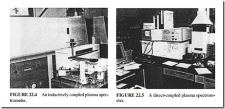
Emission Spectrographic Analysis. Emission spectrometers determine the presence of inorganic contaminants and metalloorganic oil additive elements. A film of oil is carried in this instrument on a rotating graphite wheel to a narrow gap between the wheel and a sharp- ened graphite rod electrode. The film is subjected to a high voltage arc. The energy of the arc excites the metallic elements in the oil. Each element emits a characteristic spectrum of light. The individual wear metal elements are characterized by selected lines of this spectrum. A diffraction grating is used to separate or isolate the selected lines, permitting their light intensities to be measured by photomultiplier tubes. A computer is used to convert the intensities of the light to element concentration. The results are printed for examination by the analyst.
Other types of spectrometers are the inductively coupled plasma (ICP) and direct-coupled plasma (DCP) spectrometers, shown in Figs. 22.4 and 22.5, respectively. The advantage of these instruments is the ability to utilize automatic samplers for the introduction of the sample into the instrument.
Emission spectrographic analysis is a powerful tool for determining the levels of wear metal (trace amounts). The significance of wear metals in used oils depends on the make and model of the equipment, type of service (including working environment, drain fre- quency, filter change interval, etc.). The concentration of metals increases with time. A sudden increase in concentration of metallic elements such as copper, lead, or iron indicates an increase in wear rate and possibly abnormal operating conditions. Immediate attention is required (maintenance or resampling is needed).
Trends should be developed over a period of time to determine normal operating conditions for wear metals. A judgment should not be made on a single sample analysis. The emis- sion spectrograph provides the levels of metalloorganic additive in the used oil. This provides information about the depletion of additive, oil makeup, and suitability of the oil being used.
This is the significance of common metals found:
Copper indicates wear in rocker arm bushings, wrist pin bushings, thrust washers, and other bronze or brass components.
Iron indicates wear from rings, liners, crankshaft, gears, pistons, cylinder walls, or valve train. It can appear as rust after storage.
Lead indicates wear from babbit or copper/lead bearings.
Tin indicates bearing wear when babbit overlays are used.
Silicon indicates the presence of sand, dust, or dirt entering the system. Major abrasion can occur, causing wear in ring, liner, bearing, and crankshaft.
Aluminum indicates bearing or piston wear. Attention is needed even for a slight increase because rapid wear generates larger particles which may not be detected by emission spectrography.
Particles larger than 10 to 15 1-m cannot be detected by a typical spectroscopy analysis. Particles smaller than 40 1-m cannot be discerned by the naked eye. This is the reason for having emission spectrographic analysis done in conjunction with other analysis techniques such as ferrography (wear particle analysis) or vibration analysis.
Infrared Analysis. Infrared (IR) spectrometry is another powerful method for detecting low levels of organic contaminants, water, and oil degradation products. It provides a simple and rapid technique for establishing the following:
1. The general lubricant type (paraffinic or naphthenic)
2. The presence and often the quantity of certain contaminants such as alcohols, polar solvents, and free water (but not normally dissolved moisture)
3. The depletion of additives such as antioxidants
4. The presence of lubricant degradation products resulting from oxidation and nitration
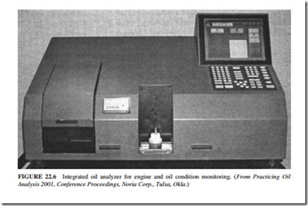
Normally, a double-beam IR spectrometer is used in the differential mode (DIR). The used oil is placed in the sampling cell of the instrument, and an unused oil is placed in the reference cell. The instrument traces a curve representing the difference between the sample and the reference. It defines clearly the spectral regions characteristic of the organic contaminant or the oil degradation products. A newer technique for DIR spectrometry uses a Fourier transform infrared (FT/IR) analyzer. It involves placing the sample in a single beam cell. The spectrum is compared to the one of the reference oil stored in the instrument computer (Fig. 22.6). The method is particularly useful in analyzing oils from natural gas–fueled engines which have high combustion temperature. These engines promote the fixation of nitrogen by combining nitrogen and oxygen from air to form NO or NO2
(termed NOx), especially in naturally aspirated four-cycle gas engines when fuel/air ratios are lean.
The FT/IR technique calculates the nitration number, which measures the nitrogen compounds in the oil resulting from fixation of nitrogen. A sudden increase in the nitration number relative to the oxidation number results in the formation of acidic materials. This increases the rate of oxidation and thickening of the oil, which results in the formation of varnish and sludge deposits. A buildup in the concentration of nitration is an indication that the engine needs tuning.
The oxidation number is also obtained from the FT/IR analyzer. It is a measure of the amount of oxidation of the oil. This is an important parameter that determines the service life of a lubricating oil. The rate of oxidation increases significantly with high-temperature operation and contamination with water and glycol antifreeze. An increase in the level of oxidation (as measured by the oxidation number) requires attention to prevent a significant increase in viscosity, organic acid formation, filter plugging sticky rings, or piston deposits and lacquering.
FT/IR spectroscopy also indicates contamination due to the presence of water, glycol antifreeze, fuel soot, or gasoline and diesel fuel, depending on the type of lubricant. When any of these contaminants are detected, the analyst will perform other tests to quantify the amount of contamination present.
Total Base Number. The total base number (TBN) indicates the total alkalinity of a lubricant. It determines the ability of the oil to neutralize harmful acidic by-products. The TBN is measured by perchloric acidic titration (ASTM Method D2896) or by potentiometric titration with hydrochloric acid (ASTM Method D4739). The latter method replaced another potentiometric titration with hydrochloric acid (ASTM D 664 for TBN) because it is more accurate and is in agreement with ASTM D2896.
The main use of the TBN is for monitoring the remaining alkalinity of overbased detergent additives present in crankcase engine oils.
Total Acid Number. The total acid number (TAN) is measured by ASTM Method D664. It is used for industrial lubricants such as turbine, hydraulic, and refrigeration oils to monitor acid buildup in service. The TAN is used as a guide to track the oxidative degradation of an oil. When the TAN reaches a predetermined level, the oil should be replaced. A sudden increase in TAN indicates abnormal operating conditions that should be investigated.
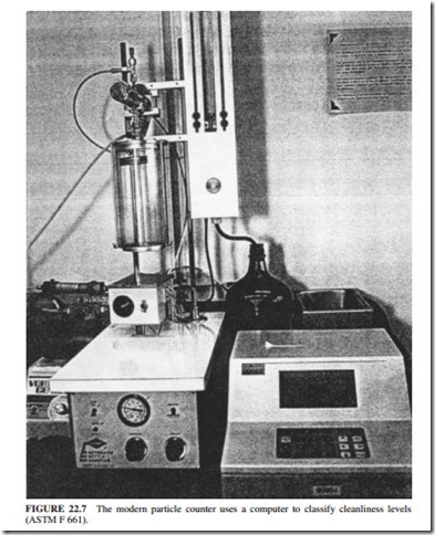
Particle Count. Many systems such as hydraulic and turbine applications circulate lubricants through narrow passageways that must be kept clean and open to allow the lubricant to flow. These systems require fine filtration of the oil in service. The particle count analysis should be included in the used-oil monitoring program to confirm the proper cleanliness of the lubricant for the service. The level of oil cleanliness for an application depends on its precision of operation, required reliability, and the system clearances. Figure 22.7 shows a modern particle counter. It uses a photometric cell to determine the classification of par- ticles in an oil sample. The cleanliness of the lubricating oil is defined by particle size ranges of 5 to 10, 10 to 25, 25 to 50, 50 to 100, and over 100 1-m. The particle count is measured in the size ranges of concern for the system being monitored. Proper sampling technique should be followed to avoid false results. The samples should also be mixed well prior to analysis.
The international standard method for classifying the size distribution of solid particles in the lubricant is the ISO Solid Contaminant Code. It typically reports particle size ranges of 5 and 15 1-m. Particles larger than 5 1-m are generally caused by foreign contamination, while particles larger than 15 1-m are wear particles in the system.
