Automatic sequence starting
It is difficult to manually control (start/stop) multiple drives simultaneously, while depending upon the various interlocks. Sometimes a large number of machine drives, in a plant or section of a plant, are required to run in a predefined sequence. When these are interlocked with each other, it can be quite difficult to start/stop the drives manually in sequence, depending on the interlocking that may be required for safety or due to the process devices.
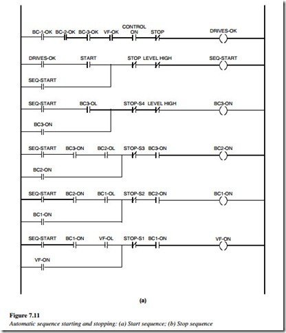
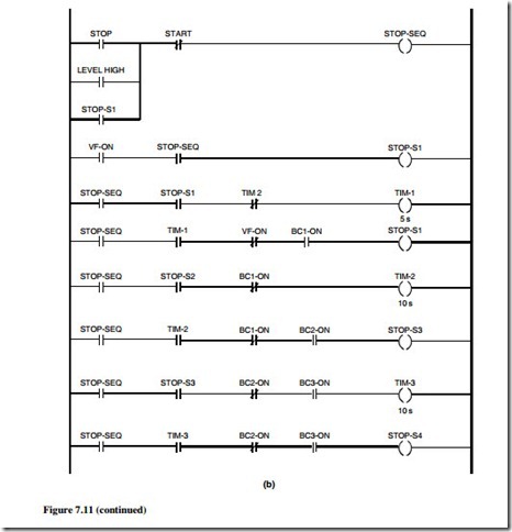
A typical automatic belt conveyor sequence system is shown in Figure 7.11. An automatic sequence start and stop of the belt conveyors is done by using a single start push button, a stop push button, a high level switch in the hopper, and timers for auto sequencing.
Reversing circuit
An interchange of any two phases reverts the direction of a three-phase motor. This will run the motor in the reverse direction.
To accomplish this reversal, two different types of control circuits are detailed as follows.
Jog type for/rev/off circuit using selector switch
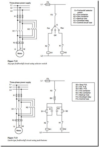
Interchanging any two leads to a three-phase induction motor will cause it to run in the reverse direction. A three-phase reversing starter shown in the main circuit (Figure.7.12) shows two contactors K1 and K2 (forward and reverse, respectively). The selector switch is of the spring return-type with the center off.
The contactor coil K1 is energized keeping the selector switch in a forward position. The contactor K1 connects the supply leads (L1, L2, and L3) to the motor leads (U, V, and W)
in the same phase sequence. This causes the motor to run in a forward direction. Keeping the selector switch in a reverse position energizes the contactor coil K2. The contactor K2 connects the supply leads L1 to W, L2 to V, and L3 to U changing the phase sequence of L1 and L2. This causes the motor to run in a reverse direction. Putting the selector switch in an off position turns off the motor.
Latch type for/rev/stop circuit using pushbuttons
The circuit discussed earlier was of the jog type, fwd/rev circuit. The circuit shown in Figure 7.13 is of the latch type, fwd/rev control.
Pressing the forward pushbutton will energize the contactor K1 coil. This in turn will connect the supply leads to the motor leads in the same phase sequence causing the motor to rotate in a forward direction.
The contactor K1 will remain energized because of the latching contact of K1. The motor will continue to run in a forward direction until the stop/reverse pushbutton is
pressed or the motor trips on overload or the protection fuse blows.
Pressing the reverse pushbutton will energize the contactor K2 coil simultaneously by de-energizing the K1 coil. This will connect the supply leads to the motor leads in a different phase sequence causing the motor to rotate in a reverse direction. The contactor K2 will remain energized because of the latching contact of K2. The motor will continue to run in a reverse direction until the stop/forward pushbutton is pressed or the motor trips on overload or the protection fuse blows.
The stop button need not be pressed before changing the direction of the rotation.


