Using test equipment
THIS CHAPTER INTRODUCES YOU TO THE TOOLS AND TEST equipment needed for printer troubleshooting. If you are unfamil iar with test equipment, read this chapter carefully. If you are an experienced troubleshooter, you might want to skip this chapter.
Small tools & materials
It might sound strange, but hand tools can often make or break your repair effort. If you have ever started a repair, then been delayed by one missing screwdriver, pair of pliers, or wrench (“you knew it was there last week”), then you know how much time and frustration can be saved by gathering the proper tools before you begin. Check your toolbox! If you do not have a toolbox just yet, now is a good time to consider what you need for electronics repairs.
Hand tools
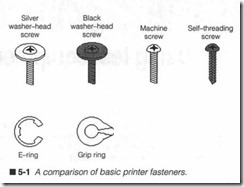
Screwdrivers are always a good place to start. Figure 5-1 illus trates six general types of screws and rings that you will likely en counter. A healthy variety of both regular and Phillips-type screwdrivers goes a long way for basic assembly, disassembly, and adjustment tasks. Avoid excessively large or unusually small screw drivers unless there is a specific need for them. Several short-shaft screwdrivers can come in handy when working in confined areas; printer assemblies can be very densely packaged. Allen-type (hexag onal hole) screws are also common, so include a set of Allen keys in your toolbox. Keep an eye out for specialty screws. Spline-type and tone-type screws are growing in popularity as manufacturers seek to keep untrained personnel out of their equipment. Fortunately, large hardware stores usually stock spline and torx drivers.
Silver washer screws are highly conductive fasteners, and are fre quently used to ensure a reliable electrical contact between as semblies. The silver machine screws are generic fasteners used almost exclusively to mount modules and printer subassemblies.
Black washer screws are anodized, which makes their surfaces nonconductive. Such fasteners are used to secure plastic parts to metal or other plastic parts. Black machine screws are typically found seeming the printer’s structural parts such as the chassis. Black self-threading screws are almost always used to secure a part to a plastic mounting hole. Be very careful to avoid stripping the plastic mounting hole; use just enough force to seat the screw, but no more. E-rings are slipped over grooves machin ed into metal axles, and are typically used to hold rotating parts (such as gears and rollers) in place on their shafts. A grip ring is similar to an e-ring, but the grip ring is used when there are no machined grooves on the axle or shaft.
Consider three types of pliers. A garden variety pair of mechanic’s pliers is useful for keeping tight hold on any nut, bolt, or other pesky part. Two pairs of needlenose pliers (one short nose, one long nose) round out the collection. Needlenose pliers are great for grabbing and holding parts in tight spaces. They also come in handy as heat sinks when soldering.
A set of small, electronics-grade, open-end wrenches work well to hold small nuts during assembly and disassembly. Wrenches should have thin bodies (for tight spaces), and should be below o/.s” (or 8 mm for metric sizes). If you have the choice between metric or U.S. wrenches, get metric. Many printers are made in Asia and the Pacific rim where metric parts are standard. A small adjustable wrench is always a good addition to a toolbox.
Because you are working with electronic systems, two sizes of wire cutters (one small and one medium) should be on hand to cut jumper wires or trim replacement component leads. A separate wire stripper should be included to remove insulation from wires or components. Resist the temptation to strip insulation using wire cutters. Even if insulation should be removed successfully, cutting blades often leave a nick or pinch in the conductor, which later might fatigue and break. If you plan to be making or repairing connectors, you might need special crimp or insertion tools to do the job. Those will vary depending on exactly what types of con nectors you need to make.
Circuit work requires a soldering iron. Invest in a good-quality sol dering pencil, something in the 25- to 30-W range. Avoid the heavy-duty, high-power soldering guns. They might work fine for plumbers, but that much power can easily destroy delicate printed circuit boards and components. Always be sure to have one or two spare tips on hand. Irons exceed 500°F at the tip. This tempera ture is a serious hazard to your personal safety, and a tremendous fire hazard as well. Be sure to park a hot soldering iron in a strong, wire frame holder. Never leave an iron unattended on a bench or table top.
Materials
To use a soldering iron, you are also going to need an ample supply of solder. Use a 60% tin, 40% lead (60/40) solder containing a resin cleaning agent. Under no circumstances should you ever use paste flux containing acids or solvents, or use solder containing acid flux (sometimes called acid core or plumber’s solder). Harsh solvents destroy delicate component leads and circuit traces.
A spool of hook-up wire can serve a variety of uses ranging from printed circuit repair and wire splices, to makeshift test leads. Solid wire (18 to 20 gauge) is often the easiest to work with, but stranded wire can be used just as readily. You might find it easier to keep several smaller spools of different colored wire so that wire can be color coded for different purposes (e.g., red for de voltage, blue for de ground, yellow for signal wires, and so on).
Include a set of alligator leads. They are available in a selection of lengths, colors, and wire gauges. Alligator leads are handy for tem porary jumping of signals during a repair, or to test the reaction of another signal in a circuit. A set of small alligator leads and a set of large alligator leads will cover you under most circumstances. In dividual alligator clips make excellent heat sinks for components during soldering or desoldering.
Heat shrink tubing provides quick, clean, and effective insulation for exposed wiring or splices. Most general-purpose electronics supply stores sell heat shrink tubing in three-foot rolls, or in pack ages of assorted sizes. You will need a heat gun to shrink the tub ing, although a blow drier usually works just as well. Heat shrink tubing is available in a selection of colors.
These are only a few of the more common tools and materials that you will need to get started. The list is by no means complete. There are literally hundreds of general- and special-purpose tools that you can use to aid your repairs, far too many to cover com pletely. Experience will be your best guide in deciding which tools and materials are best for you.
Soldering
Soldering is the most commonly used method of connecting wires and components within an electrical or electronic circuit. Metal surfaces (e.g., component leads, wires, or printed circuit traces) are heated to high temperatures, then joined together with a layer of compatible molten metal. When done correctly, soldering forms a lasting, corrosion-proof, inter-molecular bond that is mechani cally strong and electrically sound. All that is needed is an appro priate soldering iron and electronics-grade (60/40) solder. This section of the chapter looks at both regular soldering and surface mount soldering.
Soldering background
By strict definition, soldering is a process of bonding metals to gether. There are three distinct types of soldering: brazing, silver soldering, and soft soldering. Brazing and silver soldering are used when working with hard or precious metals, but soft soldering is the technique of choice for electronics work.
In order to bond wire and component leads (typically made of cop per), a third metal must be added while in its molten state. The bonding metal is known simply as solder. Several different types of solder are available to handle each soldering technique, but the chosen solder must be molecularly compatible with the metals to be bonded; otherwise, a bond will not form. Lead and tin are two common, inexpensive metals that adhere very well to copper. Un fortunately, neither metal by itself has the strength, hardness, and melting point characteristics to make them useful. Therefore, lead and tin are combined into an alloy. A ratio of approximately 60% tin and 40% lead yields an alloy that offers reasonable hardness, good pliability, and a relatively low melting point that is ideal for electronics work. This is the solder that you should use.
Although solder adheres very well to copper, it does not adhere well at all to the oxides that form naturally on its surface. Even though conductors might “look” clean and clear, some amount of oxidization is always present. Oxides must be removed before a good bond can be achieved. A resin cleaning agent (calledjl’ll..X”) can be applied to conductors before soldering. While resin is chemically inactive at room temperature, it becomes extremely active when heated to soldering temperatures. Active flux com bines with oxide and strips it away, leaving clean copper surfaces for molten solder. As a completed solder joint cools, any residual resin cools and returns to an inactive state. Never use acid or sol vent-based flux to prepare conductors. They can clean away ox ides as well as resin, but acids and solvents remain active after the joint cools. Over time, this will dissolve copper wires and connec tions, and eventually cause a circuit failure. Resin flux can be pur chased as a paste that can be brushed into conductors before soldering, but most electronic solders have a core of resin manu factured right into the solder strand itself. This is much cleaner and more convenient because resin-core solder cleans the joint as solder is applied. Such resin-core solder is much more convenient than working with flux paste.
Irons & tips
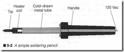
A soldering iron is little more than a resistive heating element built into the end of a long steel tube as shown in the cross-sectional di agram of figure 5-2. When 120Vac is applied to the heater, it warms the base of a tip. Any heat conducted down the cool-down tube is dissipated harmlessly to the surrounding air. This keeps the handle temperature low enough to hold comfortably.
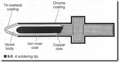
Most of the heat is channeled into a soldering tip similar to the one shown in figure 5-3. Tips often have a core of copper that is plated with iron. It is coated with a layer of nickel to stop high-tempera ture corrosion, then plated with chromium. A chromium coating renders the tip nonwettable; solder will not stick. Because solder must stick at the tip’s end, that end is plated with tin. A tin coating makes the end wettable. Tips can be manufactured in a wide range of shapes and sizes. Before you select the best tip for the job, you must understand ideal soldering conditions.
The very best electronic soldering connections are made within only a narrow window of time and temperatme. A solder joint heated between 500 to 550°F for one to two seconds will make the best connections. You must select yow- soldering iron wattage and tip to achieve these conditions. Too many arnatem technicians are content with a single soldering iron and tip, but this can present serious problems. The entire purpose of soldering irons is not to melt solder. Instead, a soldering iron is supposed to deliver heat to a joint; the joint will melt solder. A larger joint (with more numer ous or larger conductors) requires a larger iron and tip than a small joint (with fewer or smaller conductors). If you use a small iron to heat a large joint, the joint migh t dissipate heat faster than the iron can deliver it, so the j oint might not reach an acceptable soldering temperature. Conversely, using a large iron to heat a small joint will overheat the joint. Overheating can melt wire insu lation and damage printed circuit traces. The skilled technician will match wattage to the situation . Most general-purpose elec tronics work can be done using an iron below 30 W.
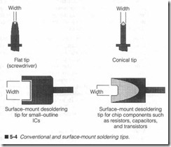
Because the end of a tip actually contacts the joint to be soldered, its shape and size can assist h eat transfer greatly. When heat must be applied across a wide area (such as a wire splice), a wide area tip should be used. A screwdriver (or .flat-blade) tip such as shown in figure 5-4 is a good choice. If heat must be directed with pin point accuracy for small, tight joints or printed circuits, a narrow blade or conical tip is the best. Two tips for surface mount desol dering are also shown in figure 5-4.
Soldering technique
First, consider these important safety points:
0 Always park your soldering iron in a secure holder while it is on.
0 Never allow a hot iron to sit freely for any length of time on a table top or anything flammable.
0 Make it a point to always wear safety glasses when soldering.
Active resin or molten solder can easily flick off the iron or joint and do permanent damage to the tissue in your eyes.
Give your soldering iron plenty of time to warm up (five minutes is usually adequate). Once the iron is at its working temperature, you should coat the wettable portion of the tip with fresh solder (this is known as tinning the iron). Rub the tip into a sponge soaked in clean water to wipe away any accumulations of debris or carbon that might have formed, then apply a thin coating of fresh solder to the tip’s end. Solder penetrates the tip to a molecular level and forms a cushion of molten solder that aids heat transfer. Re-tin the iron any time its tip becomes blackened, perhaps every few minutes or after several joints.
It also might be helpful to tin each individual conductor before ac tually making the complete joint. To tin a wire, prepare it by strip ping away :X6 to of an inch of insulation. As you strip insulation, be sure not to nick or damage the conductor. Heat the exposed copper for about one second, then apply solder into the wire, not into the iron. If the iron and tip are appropriate, solder should flow evenly and smoothly into the conductor. Apply enough solder to bond each of a stranded wire’s exposed strands. When tinning a solid wire or component lead, apply just enough solder to lightly coat the conductor’s surface. Park the soldering iron safely and al low the tinned wire(s) to cool. You will find that conductors heat faster and solder flows better when all parts of ajoint are tinned in advance.
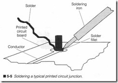
Making a complete solder joint is just as easy. Bring together each of your conductors as necessary to form the joint. For example, if you are soldering a component into a printed circuit board, insert the component leads into their appropriate locations. Place the iron against all conductors to be heated, as shown in figure 5-5. For a printed circuit board, heat the printed trace and component lead together. After about one second, flow solder gently into the conductors, not the iron. Be sure that solder flows cleanly and evenly into the joint. Apply solder for another one or two seconds,
then remove both solder and iron. Do not attempt to touch or move the join t until molten solder has set for several seconds (and cooled for at least 30 seconds) . If the j oint requires additional sol der, reheat the joint and flow in a bit more solder.
You can identify a good solder joint by its smooth, even, silvery gray appearance. Any charred or carbonized flux on the joint indi cates that your soldering temperature is too high (or that heat is being applied for too long). Remember that solder cannot flow un less the join t is hot. If it is not , solder will cool before it bond s. The result is a rough, built-up , dull-gray or blackish moun d that does not adhere very well. This is known as a cold solder joint. Cold joints can cause poor connections that translate to intermittent op eration. Fortunately, a cold joint can easily be corrected by reheat ing the j oint properly and applying fresh solder; the hard part is finding the cold joint in the first place.
Surface mount soldering
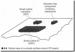
Classic printed circuit board s use through-hole components. This is the tried-and-true fabrication technique where parts are in serted on one side of the PC board, and their leads are soldered to printed traces on the other side. Surface-mounted components do not penetrate a PC board. Instead , they rest on only one side of the board as shown in figure 5-6. Metal tabs replace component lead wires. Surface mount components range from discrete compo nents, such as resistors and capacitors, to active parts, such as
transistors and integrated circuits. Even sophisticated ICs like mi croprocessors and ASICs are frequently fow1d in surface mount packag es.
During manufactur e, surface mount parts are glued into place on a PC board, then the board is brought quickly up to soldering tem peratur e in a special chamber. A wave of molten solder is passed over the board where it adheres to heated component leads and PC traces. The remaind er of the board is chemically and physically masked prior to soldering to prevent molten solder from sticking elsewhere. The finished board is then cooled slowly to prevent thermal shock to the components, masks are stripped away, and the board can be tested (or any through-hole parts can be added). This type of fabrication is calledjlow soldering, and it is similar to the principle used to mass-sold er tJu·ough-hole PC boards.
A close variation of the surface-mount manufacturing technique applies a layer of solder paste to a masked PC board before com ponents are applied, then the board is heated to flow solder into PC trace. After components are glued into place, the board is quickly reheated so solder will adhere to each component lead. The finished board is then cooled slowly. This is known as rejlow soldering. Although the specific methods of surface mount sol dering will have little impact on your troubleshooting, you should understand how surface mount components are assembled in or der to disassemble them properly during your repair.
Desoldering
Ideally, desoldering a connection involves removing the intermo lecular bond that has been formed during soldering. In reality, however, this is virtually impossible. The best that you can hope for is to remove enough solder to gently break the connection apart without destroying the joint. Desoldering is basically a game of removing as much solder as possible. Some connections are very easy to remove. For instance, a wire inserted into a printed circuit board might be removed just by reheating the joint and gently withdrawing the wire from its hole once solder is molten. You can use desoldering tools to clear away the solder itself after the connection is broken.
Surface mount components present a special problem, because it is impossible to move the part until it is desoldered completely. By using special desoldering tips, as shown in figure 5-4, all leads can be heated simultaneously so the part can be separated in one quick motion. There are also special tips for desoldering a selec tion of IC packages. Once a part is clear, excess solder can be re moved with conventional desoldering tools, such as a solder vacuum or solder wick.
Desoldering through-hole components is not as easy as it looks.
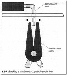
You must heat each solder joint in turn, and use a desoldering tool to remove as much solder as possible. Once each lead is clear, you will probably have to break each lead free as shown in figure 5-7. Grab hold of each lead and wiggle it back and forth gently until it breaks free. An alternate method is to heat each joint while with
drawing the lead with a pair of needlenose pliers, then clean up any excess solder later. Unfortunately, this is not possible with all components. Experience is the best teacher when it comes to desoldering.
Test equipment
Much of today’s printer troubleshooting is performed symptomati cally; that is, subassemblies are typically replaced based on the symptoms exhibited in the printed output. This is a well-under stood technique, and generally does not require the use of test equipment. On the down side, symptomatic troubleshooting is not always 100% reliable. Because new assemblies and circuits repre sent an investment of your time and money, it would benefit you to be as certain as possible of the fault before proceeding. Diagnos tics (such as PRINTERS) and test equipment can help narrow
down the problem. This section introduces you to the background, operation, and testing techniques for three major test instru ments : a multimeter, logic probe , and oscilloscope .
Multimeters
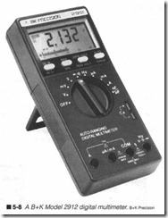
Test meters can go by many names. Some people call them multi meters or just meters, while others might refer to them as volt ohm meters (VOMs) or multitesters. Regardless of what name you choose to call them, multimeters are the handiest and most versa tile piece of test equipment that you will ever use . If your toolbox does not contain a good-quality multimeter yet , now is a good time to consider purchasing one. Even the most basic multimeters are capable of measming ac and de voltage, current, and resistance. For less than $150, you can buy a good digital multimeter that also includes features like a capacitance checker, continuity checker, diode checker, and transistor checker. Digital multimeters are eas ier to read , more tolerant of operator error, and more precise than analog multimeters . Figure 5-8 shows a B+K digital multimeter.
There are usually just two considerations when using a multirneter. First, the meter must be set to the desired function (voltage, cur rent, capacitance, etc.). Second, the range must be set properly for that function. If you are unsure what range to use, start by choos ing the highest possible range. Once you have a better idea of what readings to expect, the range might be reduced to achieve a more precise reading. If your signal exceeds the meter’s range, an “over range” warning will be displayed. Many digital multirneters are ca pable of selecting the proper range automatically (autoranging).
A multirneter can be used for two types of testing: static and dy namic. Dynamic tests are made with power applied to a circuit, while static tests are made on unpowered circuits or components. Measurements like voltage, current, and frequency are dynamic tests, but most other tests such as resistance/continuity, capaci tance, diode and transistor junction quality are static tests. The following is a review of basic multirneter measurement techniques.
Measuring voltage
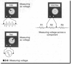
Multimeters can measure both de voltages (marked dcV or Vdc) and ac voltages (marked acV or Vac). It is important to remember that all voltages (either ac or de) must be measured in parallel with the desired circuit or component. Never interrupt a circuit and attempt to measure voltage in series with other components . Any such reading would be meaningless, and yom circuit might not even function.
Set your multimeter to its appropriate function (dcV or acV), then select the proper range. Ifyou are unsure about what range to use, start at the largest range to prevent possible damage to the meter. An autoranging multimeter will select its own range. Place your test leads across (in parallel) with the part under test, as shown in figure 5-9, and read voltage directly from the digital display. The de voltage readings are polarity sensitive, so if you read +5 Vdc and then reverse the test leads,you will see -5 Vdc. The ac voltage readings are not polarity sensitive.
Measuring current
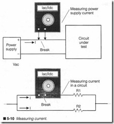
Most general-purpose multimeters allow you to measure ac current (acA or lac) and de current (dcA or Ide) in a circuit, although there are often few ranges to choose from. As with voltage measurements, current is measured in a working circuit with power applied, but current must be measured in series with the circuit or component under test. Inserting a meter in series, however, is not always an easy task. In many cases, you must physically interrupt a circuit at the point you wish to measure, then connect test leads across the break. While it might be easy to interrupt a circuit, keep in mind that you must also put the circuit back together, so use care when choos ing a point to break. Never try to read current in parallel. Current meters, by their nature, exhibit very low resistance across their leads (sometimes below 0.1 0). Placing a current meter in parallel can cause a short circuit across a component that can damage the part, the circuit under test, or your multimeter.Set your multimeter to the desired function (dcA or acA) and se lect the appropriate range. If you are unsure about the proper range, set the meter to its largest range. It might be necessary to plug one of your test leads into a different “current input” jack on the meter. Unless your multimeter is protected by an internal fuse, it can be damaged by excessive current. Make sure that the meter can handle the amount of current you are expecting.
Turn off all power to a circuit before inserting a current meter. This prevents unpredictable circuit operation when it is inter rupted. If you wish to measure power supply current feeding a cir cuit, such as in figure 5-10, break the power supply line at any convenient point (often at the supply or circuit board connec tors). Insert the meter and reapply power. Read current directly from the display. This procedure can also be used for measuring current within a circuit.
Measuring resistance
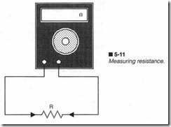
Resistance (oluns) is the most common static measurement that your multimeter is capable of. This is a handy function, not only for checking resistors, but for checking other resistive elements such as wires, connectors, motors, solenoids, and some semiconductor components. Resistance is measured in parallel across components with all circuit power off, as shown in figure 5-11. It might be nec essary to remove at least one component lead from its circuit to prevent interconnections with other components from causing false readings.
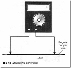
Ordinary resistors can be checked simply by switching to a resis tance function and selecting the proper range. Many multimeters can reliably measure resistance up to 20 Mn. Place your test leads across the component and read resistanc e directly from the dis play. If resistance exceeds the selected range, the display will in dicate an overrange or infinite resistance condition. Continuity checks are made to ensure a reliable , low-resistance connection between two points. For example, you could check the continuity of a cable between two connectors to ensw·e that both ends are connected properly. Set your multimeter to a low resistance scale, then place your test leads across both points to measure, as shown in figure 5-12. Ideally, good continuity should be about 0 n.
Checking a capacitor
There are two methods of checking a capacitor using your multi meter. If your meter is equipped with a built-in capacitance checker, all you need to do is select the capacitance function and set the desired range. You might have to place test probes in par allel across the capacitor under test, or you might have to remove the capacitor and insert it into a special fixture on the meter’s face. A capacitance checker will usually display capacitance directly in microfarads (J.!F) or picofarads (pF). As long as your reading is within the tolerance of the capacitor’s marked value, you know the part is good.
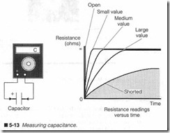
If your multimeter is not equipped with an internal capacitor checker, you could use the resistance ranges to approximate the quality of a capacitor. This type of check provides a “quick and dirty” judgm ent of whether the capacitor is good or bad. The prin ciple behind this is simple. All ohmmeter ranges use an internal battery to supply current for the component under test. When that current is supplied to a working capacitor, as shown in figure 5-13, it will charge the capacitor. Charge accumulates as the ohmmeter is left connected, and can be seen as changing resistance on the ohmmeter display. When first connected across an ohmmeter, the capacitor will draw a relatively large amount of current; this reads as low resistance. As the capacitor charges, it draws less and less current, so resistance appears to increase. Ideally, a fully charged capacitor draws no current, so your resistance reading should climb to infinity. When a capacitor behaves this way, it is probably good.
You are not actually measuring resistance or capacitance here, but only the profile of a capacitor’s charging characteristic. If the ca pacitor is extremely small, or is open-circuited , it will not charge substantially, so it will instantly read infinity. If a capacitor is partially (or totally) short-circuited, it will not hold a charge, so you might read 0 Q (or resistance might climb to some level below in finity and remain there). In either case, the capacitor is probably defective. If you doubt your readings, check several other capaci tors of the same value and compare readings. Be sure to make this test on a moderate to high resistance scale. A low resistance scale might charge to infinity too quickly for a clear reading.
Semiconductor checks
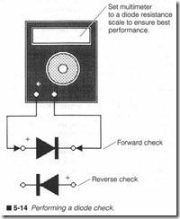
Many multimeters offer a semiconductor junct ion checker for diodes and transistors. Meters equipped with a “diode” range in their resistance function can be used to measure the static resis tance of most common diodes in their forward or reverse-biased conditions, as shown in figure 5-14. Select the diode range from your meter’s resistance function and place test leads across the diode in the “forward” direction. A working silicon diode should exhibit a resistance between about 450 and 700 Q,which will read directly on your meter. Reverse your test leads to reverse-bias the diode. Because a working diode should not conduct at all in the re verse direction, you should read infinite resistance.
A shorted diode will exhibit a very low resistance in the forward and reverse-bias directions. This indicates a shorted semiconduc tor junction. Be certain that at least one of the diode’s two leads is removed from the circuit before testing. This will prevent its in terconnections with other components from causing a faulty read ing. An opened diode will exhibit very high resistance (usually infinity) in both its forward and reverse directions. In this case, the semiconductor junction is open-circuited. If you feel unsure how to interpret your measurements, test several other compara ble diodes and compare readings.
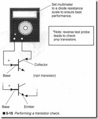
Transistors can be checked in several ways. Some multimeters feature a built-in transistor checker that measures a transistor’s gain (or hfe) directly. If your meter offers a transistor checker, in sert your transistor into the test fixture on the meter’s face in its correct lead orientation (emitter, base, and collector). Manufac turer’s specifications can tell you whether a gain reading is correct for a particular part. A low (or zero) reading indicates a shorted transistor, while a high (or infinite) reading suggests an open-cir cuited transistor.Your meter’s diode checking feature can also be used to check a bipolar transistor’s base-emitter and base-collector junctions as shown in figure 5-15. Each junction acts just like a diode junction. Test one junction at a time. Set your multimeter to its diode range, then place its test leads across the base-collector junction. If your transistor is npn, place the positive test lead at the base. This should forward-bias the base-collector junction and cause a normal amount of diode resistance. Reverse your test leads across the base-collec tor junction. It should now be reverse-biased and show infinite re sistance. Repeat this procedure for the base-emitter junction.
If your transistor is pnp, your test lead placement must be re versed. For example, a forward-biased junction in an npn transis tor is reverse-biased in a pnp transistor. You can refer to manufacturer’s specification sheets to determine which leads in the transistor are the base, emitter, and collector. As a final check, measure the resistance from emitter to collector. You should read infinite resistance in both directions. Although this is not a diode junction, short circuits can develop during a transistor failure, which might not appear across normal junctions; Replace any diode with an open or shorted junction, or a short from emitter to collector.
Logic probes
The problem with most multim eters is that they do not relate well to digital logic circuits. A multimeter can certainly measure whether a logic voltage is on or off, but if that logic level changes quickly, a de voltmeter function cannot track it properly. Logic probes provide a fast and easy means of detecting steady-state or alternating logic levels. Some logic probes can detect logic pulses faster than 50 MHz.
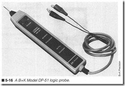
Logic probes are rather simple-looking devices, as shown in figure 5-16. A probe might be powered from its own internal battery, or from the circuit under test. Connect the probe’s ground lead to a convenient circuit ground. Ifa probe is powered from the circuit un der test, attach its power lead to a logic supply voltage in the circuit. A small panel on the probe’s body holds several LED indicators and a switch that allows the probe to work with two common logic fam ilies (TIL and CMOS). You might find TTL and CMOS devices mixed into the same circuit, but one family will usually dominate.
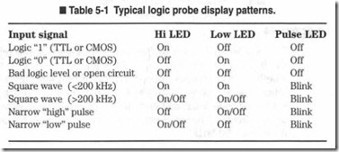
When the metal probe tip is touched to an IC lead, its logic state is displayed on one of the three LED indicators, as shown in Table 5-1. Typical choices are “logic 0,” “logic 1,” and “pulse” (or “clock”). Logic probes are most useful for troubleshooting working logic cir cuits where logic levels and clock signals must be determined quickly and accurately.
Oscilloscopes
Oscilloscopes offer a tremendous advantage over multirneters and logic probes. Instead of reading signals in terms of numbers or lighted indicators, an oscilloscope will show voltage versus time on a visual display. Not only can you observe ac and de voltages , but it enables you to watch digital voltage levels, high-energy motor pulses, or other unusual signals occur in real time. Ifyou have used
Controls
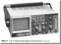
an oscilloscope in the past, you know just how useful it can be. Os cilloscopes such as the one shown in figure 5-17may appear some what overwhelming at first, but many of their operations work the same way regardless of what model you are working with.
In spite of the wide variations of features and complexity between models, most controls are common to the operation of every oscil loscope. Controls fall into four categories: horizontal (time base) signal controls, vertical (amplitude) signal controls, “housekeep ing” controls, and optional (enhanced) controls.
Since an oscilloscope displays voltage versus time, adjusting either voltage or time settings will alter the display. Horizontal controls manipulat e the left-to-right time appearance (sweep) of the volt age signal. Your oscilloscope’s master time base is adjusted using a TIME/DIV knob or button. This sets the rate at which voltage sig nals are swept onto the screen. Smaller settings allow shorter events to be displayed more clearly, and vice versa. Remaining horizontal controls include a horizontal display mode selector, sweep trigger selection and sensitivity, trigger coupling selection, and trigger source selection. Your particular oscilloscope may of fer additional controls.
An adjustment to an oscilloscope’s voltage sensitivity will also alter your display. Vertical controls affect the deflection (up-to-down) appearance of your signal. An oscilloscope’s vertical sensitivity is controlled with the VOLTS/DIY knob. When sensitivity is in creased (VOLTS/DIY becomes smaller), signals will appear larger vertically. Reducing sensitivity will make signals appear smaller vertically. Other vertical controls include coupling selection, verti cal mode selection, and a display inverter switch.
Housekeeping controls handle such things as oscilloscope power, trace intensity, graticule intensity, trace magnification, horizontal trace offset, vertical trace offset, and a trace finder-any control that affects the quality and visibility of a display. Your oscilloscope may have any number of optional controls depending on its cost and complexity, but cursor and storage controls are some of the most common. Many scopes offer horizontal and vertical on-screen cursors to aid in the evaluation of waveforms. Panel controls allow each cursor to be moved around the screen. The distance between cursors is then converted to a corresponding voltage, time, or fre quency value, and that number is displayed on the screen in ap propriate units. Storage oscilloscopes allow a screen display to be held right on-screen, or in memory within the scope to be recalled on demand.
Oscilloscope specifications
Oscilloscopes have a variety of important specifications that you should be familiar with when choosing and using an oscilloscope.
The first specification to know is bandwidth. It represents the range of frequencies that the scope can work with. This does not necessarily mean that all signals within that bandwidth can be dis played accurately. Bandwidth is usually rated from de to some maximum frequency (often in megahertz or MHz). For example, an inexpensive oscilloscope might cover de to 20 MHz, while a more expensive model might work up to 150 MHz or more. Good bandwidth is very expensive, more so than any other feature.
The vertical deflection (or vertical sensitivity) is another important specification. It is listed as the minimum to maximum volts/DIY set tings that are offered, and the number of steps that are available within that range. A typical model might provide vertical sensitivity from 5 mV/DIV to 5 V/DIV broken down into 10 steps. A time base (or sweep range) specification represents the minimum to maxi mum time base rates that an oscilloscope can produce, and the nlilllber of increments that are available. A range of 0.1 JlSIDN to 0.2 s/DN in 20 steps is not unusual. You will typically find a greater number of time base increments than sensitivity increments.
There is a maximum voltage input that can be applied to an oscil loscope input. A maximum voltage input of 400 V (de or peak ac) is common for most basic models, but more sophisticated models can accept inputs greater than 1,000 V. An oscilloscope’s input will present a load to whatever circuit or component it is placed across. This is called input impedance, and is usually expressed as a value of resistance and capacitance. To guarantee proper op eration over a model’s entire bandwidth, select a probe with load characteristics similar to those of the oscilloscope. Most oscillo scopes have an input impedance of 1 MQ with 10 to 50 pF of ca pacitance.
The accuracy of an oscilloscope represents the vertical and hori zontal accuracy of the fmal CRT display. In general, oscilloscopes are not as accurate as dedicated voltage or frequency meters. A typical model can provide ±3% accuracy, so a 1-V measurement can be displayed between 0.97 V to 1.03 V. Keep in mind that this does not consider human errors in reading the CRT marks (or graticule). However, because the strength of an oscilloscope is its ability to graphically display complex and fast signals, 3% accu racy is usually adequate.
Oscilloscope start-up procedures
Before you begin taking measurements, a clear, stable trace must be obtained (if not already visible). If a trace is not visible, make sure that any CRT screen storage modes are off, and that intensity is turned up at least 50%. Set triggering to its “automatic” mode and adjust the horizontal and vertical offset controls to the center of their ranges. Be sure to select an “internal” trigger source, then adjust the trigger “level” until a trace is visible. Vary your vertical offset if necessary to center the trace across the CRT.
If a trace is not yet visible, use the “beam fmder” to reveal its loca tion. A beam finder simply compresses the vertical and horizontal ranges. This forces a trace onto the display and gives you a rough idea of its relative position. After your trace is moved into position, adjust your focus and intensity controls to obtain a crisp, sharp trace. Keep intensity as low as possible to improve display accu racy, and preserve phosphors in the CRT.
Your oscilloscope probe must be calibrated before use. Calibration is a quick and straightforward operation that requires only a low amplitude, low-frequency square wave. Many models have a built in “calibration” signal generator (a 1-kHz, 300-mV square wave with a 50% duty cycle). Attach your probe to the desired input jack, then place it across the calibration signal. Adjust your hori zontal (Time/DIV) and vertical (Volts/DIV) controls so that one or two complete cycles are clearly shown on the CRT.
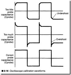
Observe the characteristics of your test signal, as shown in figure 5-18. If the square wave’s corners appear rounded, there might not be enough probe capacitance (Cprobe). Spiked square wave cor ners suggest too much capacitance in the probe. Either way, the scope and probe are not matched properly. You must adjust the probe capacitance to establish a good electrical match; otherwise, signal distortion might result. Slowly adjust the variable capaci tance on your probe until the corners of your calibration signal are as square as possible. If you cannot achieve a clean square wave, try a different probe.
Voltage measurements
The first step in any voltage measurement is to set your normal trace (or baseline) where you want it. Normally, a baseline is placed along the center of the graticule during start-up, but it can be placed anywhere so long as it is visible. To establish a baseline, switch your input coupling control to its “ground” position. This disconnects the input signal and grounds the charmel to ensure a zero reading. Adjust the vertical offset control to shift the baseline wherever the zero reading is to be. If you have no particular pref erence, simply center it in the CRT.
To measure de, set your input coupling switch to its “de” position, then adjust the Volts/DIV control to provide the desired amount of sensitivity. If you are unsure about what sensitivity is appropriate, start with a very low sensitivity (a large Volts/DIV setting), then carefully increase the sensitivity (reduce the Volts/DIV setting) af ter your signal is connected. This prevents a trace from simply jumping off the display when an unknown signal is first applied. If your signal does happen to leave the visible display, you could re duce sensitivity (increase the Volts/DIV setting) to make the trace visible again.
For example, suppose you were measuring a +5-Vdc power sup ply output. If Volts/DIV is set to 5 V/DIV, each major vertical division represents 5 V, so your +5-Vde signal should appear one full division above your baseline (5 V/DIV x 1 division = 5 V), as shown in figure 5-19. At a Volts/DIV setting of 2 V/DIV, the same +5-V signal would now appear 2.5 divisions above your baseline (2 V/DIV x 2.5 divisions= 5 V). If your input signal were a nega tive voltage, the trace would appear below the baseline, but it would read the same way.
The ac signals can also be read directly from the oscilloscope. Switch your input coupling control to the “ac” position, then set a baseline just as you would for de measurements. If you are unsure about how to set the vertical sensitivity, start with a low sensitivity (a large Volts/DIV setting), then slowly increase the sensitivity (reduce the Volts/DIV scale) after a signal is connected. Keep in mind that ac voltage measurements on an oscilloscope will not match ac voltage readings on a multimeter. An oscilloscope dis plays instantaneous peak values for a waveform, while ac volt meters measure in terms of rms (root mean square) values. To convert an rms value to peak, multiply rms x 1.414. To convert a peak voltage reading to rms, divide peak/1.414.
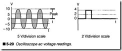
When actually measuring an ac signal, it might be necessary to ad just the oscilloscope’s trigger level control to obtain a stable (still) trace. As figure 5-20 shows, signal voltages can be measured di rectly from the display. For example, the sinusoidal waveform of figure 5-20 varies from -10 to +10 V. If scope sensitivity were set to 5 V/DIV, its peaks would be two divisions above and below the baseline. Because this is a peak measurement, an ac voltmeter would show the signal as peak/1.414, or [10/1.414] 7.07 Vnns·
Time & frequency measurements
An oscilloscope is perfect for measuring critical signal parameters such as pulse width, duty cycle, and frequency. It is the horizontal sensitivity (Time/DIV) control that comes into play with time and frequency measurements. Before making any measurements, you must frrst obtain a clear baseline as you would for voltage mea surements. When a baseline is established and a signal is con nected, adjust the Time/DIV control to display one or two complete cycles of the signal.
Figure 5-21 illustrates two typical period measurements. With Volt /DIV set to 5 ms/DIV, the sinusoidal waveform repeats every two divisions. This represents a period of [5 ms/DIV x 2 divisions] 10 ms. Because frequency is the simple reciprocal of the period, frequency can be calculated directly from period. A period of 10 ms would represent a frequency of (Yto ms) 100 Hz. This also works for square waves and other nonsinusoidal waveforms. The square wave in figure 5-21 repeats every four divisions. At a TIME/DIV setting of 1 ms/DIV, its period would be 4 ms. This corresponds to a frequency of (X ms) 250 Hz.Instead of measuring the entire period of a pulse cycle, you can also read the time between any two points of interest. For the square wave in figure 5-21, you could read its pulse width to be 1ms. You could also read the low portion of the cycle as a pulse width of 3 ms (added together for its total period of 4 ms). A signal’s duty cycle is simply the ratio of a signal’s ON time to its total period expressed as a percentage. For example, a square wave on for 2 ms and off for 2 ms would have a duty cycle of [2 ms/(2 ms + 2 ms) x 100%] 50%. For an on time of 1ms and an off time of 3 ms, its duty cycle would be [1 ms /(1 ms + 3 ms) x 100%] 25%. Use caution in duty cycle measurements.
