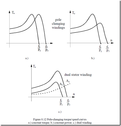
Changing the number of poles, 2p1, changes the ideal no-load speed n1 = f1/p1 accordingly. In Chapter 4, we discussed pole-changing windings and their
connections of phases to produce constant power or constant torque for the two different pole numbers 2p2 and 2p1 (Figure 8.12).
The IM has to be sized carefully for the largest torque conditions and with careful checking for performance for both 2p1 and 2p2 poles.
Switching from 2p2 to 2p1 and back in standard pole-changing (p2/p1 = 2 Dahlander) windings implies complicated electromechanical power switches.
Better performance, new pole-changing windings (Chapter 4) that require only 2 single throw power switches have been proposed recently.
For applications where the speed ratio is 3/2, 4/3, 6/4, etc. and the power drops dramatically for the lower speed (wind generators), dual windings may be used. The smaller power winding will occupy only a small part of slot area. Again, only two power switches are required-the second one of notably smaller power rating.
Pole-changing windings are also useful for wide speed range ωmax/ωb > 3 power induction motor drives (spindle drives or electric (or hybrid) automobile electric propulsion). This solution is a way to reduce motor size for ωmax/ωb > 3.
8.4 VARIABLE FREQUENCY METHODS
When changing frequency f1, the ideal no-load speed n1=f1/p1 changes and so does the motor speed for given slip.
Frequency static converters are capable of producing variable voltage and frequency, Vs, f1. A coordination of Vs with f1 is required.
Such a coordination may be “driven” by an optimization criterion or by flux linkage control in the machine to secure fast torque response.
The various voltage-frequency relationships may be classified into 4 main categories:
– V/f scalar control
– Rotor flux vector control
– Stator flux vector control
– Direct torque and flux control
Historically, the V/f scalar control was first introduced and is used widely today for open loop speed control in driving fans, pumps, etc., which have the load torque dependent on speed squared, or more. The method is rather simple, but the torque response tends to be slow.
For high torque response performance, separate flux and torque control much like in a d.c. machine, is recommended. This is called vector control.
Either rotor flux or stator flux control is performed. In essence, the stator current is decomposed into two components. One is flux producing while the other one is torque producing. This time the current or voltage phase and amplitude and frequency are continuously controlled. Direct torque and flux control (DTFC) [2] shows similar performance.
Any torque/speed curve could thus be obtained as long as voltage and current limitations are met. Also very quick torque response, as required in servodrives, is typical for vector control.
All these technologies are now enjoying very dynamic markets worldwide.
8.4.1 V/f scalar control characteristics
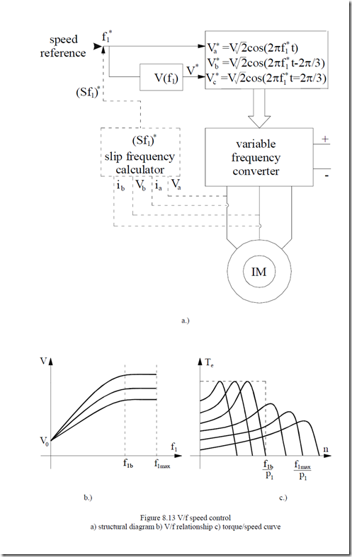
The frequency converter, which supplies the motor produces sinusoidal symmetrical voltages whose frequency is ramped for starting. Their amplitude is related to frequency by a certain relationship of the form
V = V0 + K (f ) f0 1 ⋅ 1 (8.27)
V0 is called the voltage boost destined to cover the stator resistance voltage at low frequency (speed).
Rather simple K0(f1) functions are implemented into digitally controlled variable frequency converters (Figure 8.13).
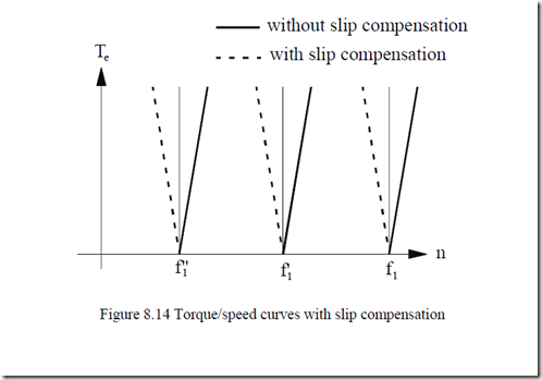
As seen in (Figure 8.13 a), a slip frequency compensator may be added to reduce speed drop with load (Figure 8.14).
Safe operation is provided above f1min = 3 Hz as torque response is rather slow (above 20 milliseconds).
Example 8.2 V/f speed control
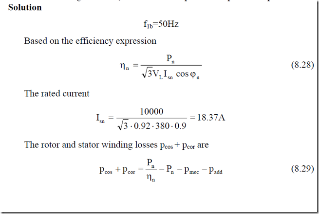
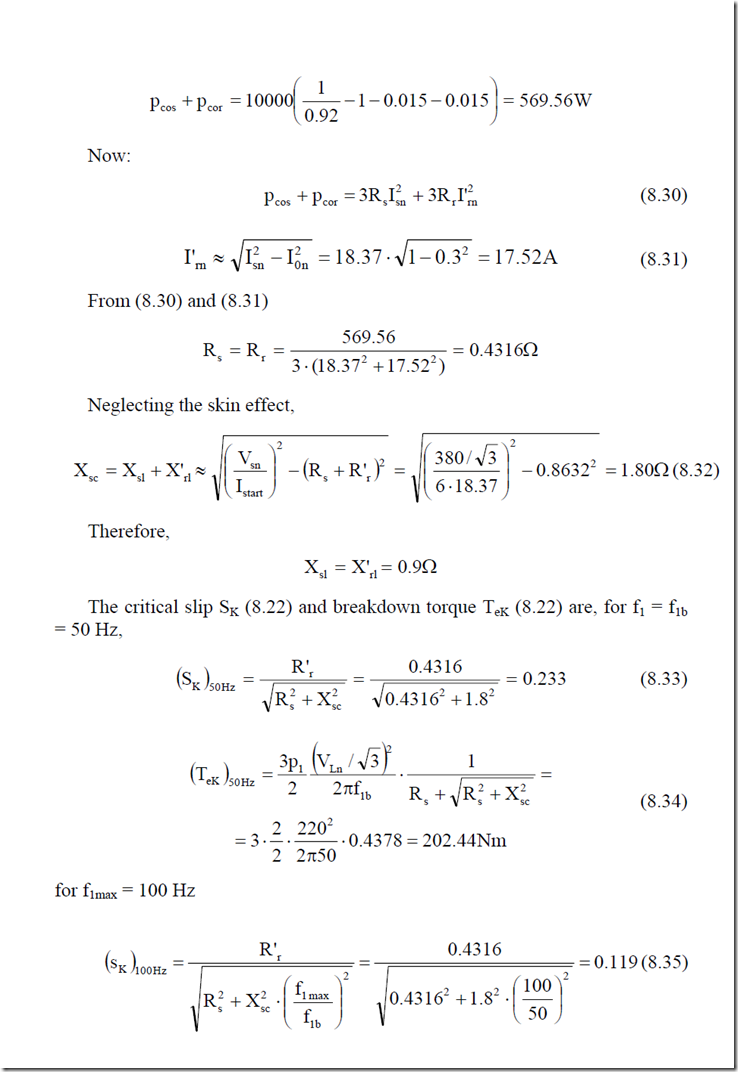
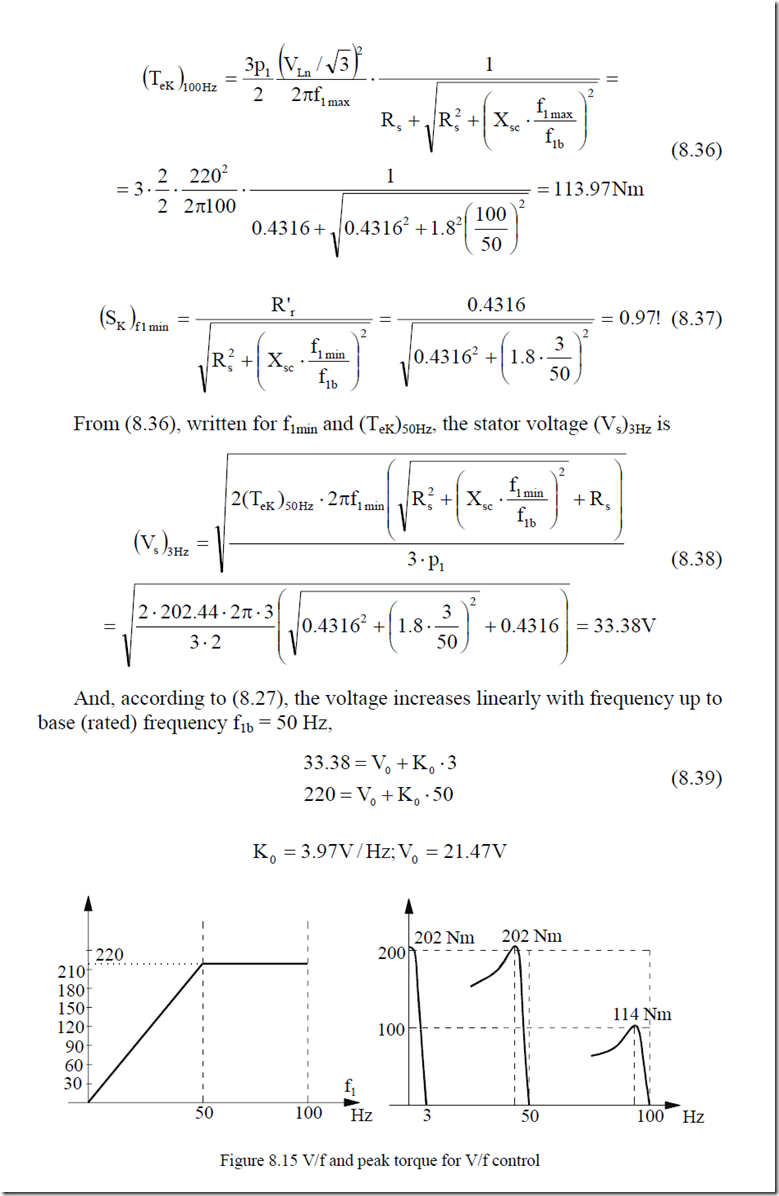
An induction motor has the following design data: Pn = 10 kW, VLn = 380 V (Y), f1b = 50 Hz, ηn = 0.92, cosφn = 0.9, 2p1 = 4, Istart/In = 6/1, I0/Isn = 0.3, pmec = 0.015Pn, padd = 0.015Pn; core losses are neglected and Rs = R′r and Xsl = X′rl. Such data are known from the manufacturer. Let us calculate: rated current, motor parameters Rs, Xsl, X1m, critical slip SK and breakdown torque TeK at f1b, and f1max for rated voltage; voltage for critical slip SK and minimum frequency f1min = 3 Hz to provide rated breakdown torque.
Find the voltage boost V0 for linear V/f dependence up to base speed.
The results are synthesized on Figure 8.15. Toward minimum frequency f1min = 3 Hz, the neglect of magnetizing reactance branch in the critical slip calculation may produce notable errors.
A check of stator current and torque at (SK)3Hz = 0.97, Vsn = 33.38 V, f1min = 3 Hz is recommended. This aspect suggests that assigning a value for voltage boost V0 is a sensitive issue.
Any variation of parameters due to temperature (resistances) and magnetic saturation (inductances) may lead to serious stability problems. This is the main reason why V/f control method, though simple, is to be used only with light load start applications.
8.4.2 Rotor flux vector control
As already mentioned, when firm starting or stable low speed performance is required, vector control is needed. To start, let us reconsider the IM equations for steady state (Chapter 7, paragraph 7.10, Equations (7.97) and (7.98)).
IsIR’ R’s − V= − ωs = − ωj 1jSΨ1Ψr s for V′r = 0 (cage rotor) (8.40)
r r
Also from (7.95),
Ψs = LL’1mr ⋅Ψ’r +Lsc Is ;I’r = ΨL”rr − LL’1mr ⋅Is (8.41)
The torque (7.100) is,
Te = 3p1Ψ’ I’r r (8.42)
It is evident in (8.40) that for steady state in a cage rotor IM, the rotor flux and current per equivalent phase are phase-shifted by π/2. This explains the torque formula (8.42) which is very similar to the case of a d.c. motor with separate excitation.
Separate (decoupled) rotor flux control represents the original vector control method. [4]
Now from (8.41) and (8.40),
Is = ‘r + jsω1 L’r ⋅ Ψ’r ;Tr = L’ / R’r r Ψ
L1m R’r L1m
or, with Ψ′r along real axis,
(8.43)
Is = IM + jI ;IT M = Ψr /L ;I1m T = jSω1Tr ⋅IM
(8.44)
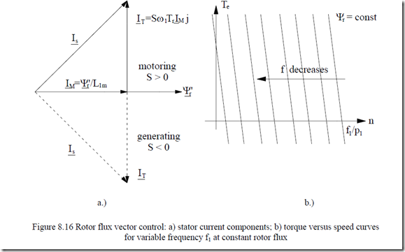
Equations (8.43) and (8.44) show that the stator current may be decomposed into two separate components, one, IM in phase with rotor flux Ψr called flux current, and the other, shifted ahead 900, IT, called the torque current.
With (8.43) and (8.44), the torque equation (8.42) may be progressively written as
Te = 3p1 LL’21rm ⋅IM ⋅IT = 3p1ΨR” S2rr ω1 (8.45)
Consequently, for constant rotor flux, the torque/speed curve represents a straight line for a separately excited d.c. motor (Figure 8.16).
As expected, keeping the rotor flux amplitude constant is feasible until the voltage ceiling in the frequency converter is reached. This happens above the base frequency f1b. Above f1b, Ψr has to be decreased, as the voltage is constant. Consequently, a kind of flux weakening occurs as in d.c. motors.
The IM torque-speed curve degenerates into V/f torque/speed curves above base speed.
As long as the rotor flux transients are kept at zero, even during machine transients, the torque expression (8.45) and rotor Equation (8.40) remain valid. This explains the fastest torque response claims with rotor flux vector control. The bonus is that for constant rotor flux the mathematics to handle the control is the simplest. This explains enormous commercial success.
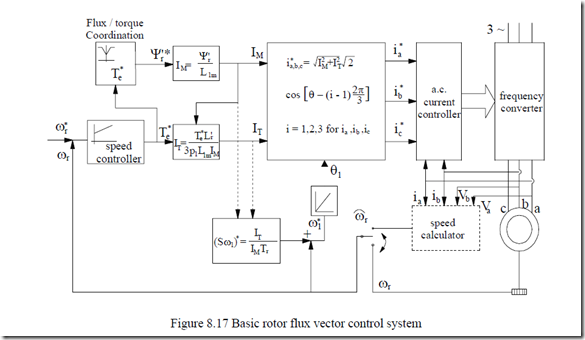
A basic structural diagram for a rotor flux vector control is shown on Figure 8.17.
The rotor flux and torque reference values are used to calculate the flux and torque current components IM and IT as amplitudes. Then the slip frequency (Sω1) is calculated and added to the measured (or calculated on line) speed value ωr to produce the primary reference frequency ω1*. Its integral is the angle θ1 of rotor flux position. With IM, IT, θ1 the three phase reference currents ia*, ib*, ic* are calculated.
Then a.c. current controllers are used to produce a pulse width modulation (PWM) strategy in the frequency converter to copy the reference currents. There are some delays in this “copying” process but they are small, so fast response in torque is provided.
Three remarks are in order.
• to produce regenerative braking it is sufficient to reduce the reference speed ωr* below ωr; IT will become negative and so will be the torque
• The calculation of slip frequency is heavily dependent on rotor resistance (Tr) variation with temperature.
• For low speed, good performance, the rotor resistance has to be corrected on line.
Example 8.3 Rotor flux vector speed control
For the induction motor in example 8.2 with the data 2p1 = 4, Rs = Rr =
0.4316 Ω, L = L‘ = −3 H ,

![]() and L1m ≈ I0m ⋅ π⋅V2s f1b − Lsl = 18.37⋅0.3⋅314 = 0.12427H , the rotor flux magnetizing current IM = 6A and the torque current IT = 20A.
and L1m ≈ I0m ⋅ π⋅V2s f1b − Lsl = 18.37⋅0.3⋅314 = 0.12427H , the rotor flux magnetizing current IM = 6A and the torque current IT = 20A.
For speed n = 600 rpm, calculate the torque, rotor flux Ψr, stator flux slip frequency Sω1, frequency ω1, and voltage required.
Solution
The rotor flux Ψ′r (8.44) is
Ψ =’r L1m ⋅IM = 0.12427⋅6 = 0.74256Wb
Equation (8.45) yields
Te = 3p1 LL’21mr IM ⋅IT = 3 2⋅ ⋅ 2.866 10×0.12427−3 + 0.2 12427 ⋅6×20 = 87.1626Nm
The slip frequency is calculated from (8.44)
![]() Sω =1 T1r IIMT = 206 ⋅ 0.124170.+43162.866×10−3 =11.30rad/s
Sω =1 T1r IIMT = 206 ⋅ 0.124170.+43162.866×10−3 =11.30rad/s
Now the frequency ω1 is
To calculate the voltage, we have to use Equations. (8.40) and (8.41) progressively.
Ψs = L1m ⋅L I1m M + Lsc ⋅(IM + jI )T = L Is M + jL Isc T (8.46)
L’r
So the stator flux has two components, one produced by IM through the noload inductance Ls = Lsl + L1m and the other produced by the torque current through the shortcircuit inductance Lsc.
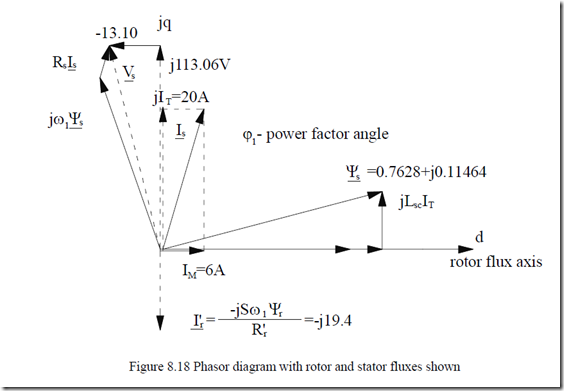
Ψs = (2.866 10× −3 + 0.12427) 6⋅ + j 2 2.⋅ ⋅ 866 10× −3 ⋅20 = 0.7628+ j 0.⋅ 11464
(8.47)
The results in terms of fluxes and voltage are summarized in Figure 8.18
For negative torque (regenerative braking) only IT becomes negative and so does the slip frequency Sω1. Now from (8.40):
![]() Vs = 13.102 +113.062 =113.81 V
Vs = 13.102 +113.062 =113.81 V
Let us further exploit the torque expression Te which may be alternative to (8.42).
(8.42).
Te = 3p Re(j1 Ψs Is *) = 3p (L1 s − L )Isc M ⋅IT (8.48)
Also the rotor current (8.38) is
I’r = Sω1 L1R’mIr M (8.49)
Torque Equation (8.48) may be interpreted as pertaining to a reluctance synchronous motor with constant high magnetic saliency as Ls/Lsc > 10 – 20 in general.
This is true only for constant rotor flux.
The apparent magnetic saliency is created by the rotor current I′r which is opposite to jIT in the stator (Figure 8.18) to kill the flux in the rotor along axis q. The situation is similar to the short-circuited secondary effect on the transformer equivalent inductance.
Stator flux vector control may be treated in a similar way. For detailed information on advanced IM drives see References [5,6].
